Behaviour of cells in parallel take 2

* To simulate morning transition from battery to solar power, gradually lower draw over an hour or so, smoothly switching over to charging.
I'm expecting virtually no balancing current flowing between the cells, because any balancing current would be overshadowed by the charging current.
That's going to require a bunch of code writing and hardware that my aging brain is going to explode with. Nevertheless I am more than willing to try it with assistance from some brilliant sketch writer. I have no problem getting the hardware and such together.
In the meantime while I wait for some assistance with that avenue of testing I am running some standard C/D/C cycles.
I have increased the rest period to 30min between the cycles to allow the cells to equalize. This was necessary for the second set of cells which were different chemistries and different IR.
I will explain.
OK first test. 4 Sony NCR18650GA cells.
Cell 1 NCR18650GR 23.440mΩ
Cell 2 NCR18650GR 23.730mΩ
Cell 3 NCR18650GR 24.280mΩ
Cell 4 NCR18650GR 23.510mΩ

This is the trace of completed C/D/C cycles. This test was charge to 4.1V@1A discharge to 3.0V @ 1A, 10 min rest between.
As you can see very little difference in the cells response to the load. The glitches at 7:00 was some adjustments being made to the iCharger X8.
1610371116342.png
The second set of cells were a little more radical. I also changed the voltage to 4.2V all other parameters stayed the same.
Cell 1 #16 39.43mΩ 4.150V ICR189650-26J
Cell 2 #17 39.74mΩ 4.146V ICR189650-26J
Cell 3 # 21 13.70mΩ 4.132V INR18650-25R
Cell 4 # 22 14.04mΩ 4.130V INR18650-25R
Cells with different chemistry similar capacity and vastly different IR.
Initially I had a 10 min rest but after looking at the trace decided to give the rest 30 min to allow equalization to occur.
Observe how each cell responds to the load.
1610371527142.png
There you have it.
More tests coming up.
Wolf
 
Last edited:
Now it's going to get interesting
Here is what was inserted at 10pm est

Edit: I forgot to mention C/D/C to 4.2V ,3.0V @1A

Cell #ModelmAhOPUS mAhIRV
41UR18650Y200071191.314.153
42UR18650H1900153753.234.112
43UR18650E2000187437.284.13
44LGDBB118652600164160.014.1
Lets see what this brings.

Wolf
 
Last edited:

It looks like you've fully soldered all the wire leads going into the screw terminals. I used to do it in the past too, and it caused overheating and melting in at least 2 cases. Probably not an issue for a temporary build, but make sure to at least re-tighten the screws over time.

I believe the industry standard now is to attach ferrules on all multi-strand wires in such cases. Standard practice before was to solder just the tip (like the last 1mm) to prevent the strands from coming apart.

Here's some more indepth discussion:
 
It looks like you've fully soldered all the wire leads going into the screw terminals. I used to do it in the past too, and it caused overheating and melting in at least 2 cases. Probably not an issue for a temporary build, but make sure to at least re-tighten the screws over time.
Yes I am aware of that thank you for pointing it out. I have every ferrule known to mankind and was going to do that before I did the permaboard. I may actually solder the leads directly to the INA260 to eliminate any potential resistance created by the terminal blocks. The screws on the other hand are tight as I just changed to the INA260 from the INA219. But ferrules tonight for sure.
On another note it appears that Cell #3 the UR18650E is taking the brunt of the torture and the LG is holding out till the end. Fascinating! Mixing these cells with different capacity and IR makes a nice colorful trace. So far temperature has really not been an issue. We certainly don't have a bus voltage deviation anymore thanks to your insight into the INA219.
Wolf
1610454602915.png
Update: The finished 3 cycle trace.
1610476465137.png
Next 3 good cells and 1 bad one.
 
Last edited:
Looks good. Then people can stop arguing that the voltage is the deal breaker here :p Ie that voltage differs. What differs is different cell types and when they deliver the energy in the voltage range. And it can clearly be seen. Thats also why i point out that if you for instance state 1A max per cell its in real life totally different. Easily can be 50% difference and thats why you also need to arrange the packs properly when having larger spread and also choose the fuse wisely :)

Looking forward to numbers like max spread among the most uneven cell and also the same on exactly same type of cells but different ages (Probably slight variation of IR)
I will openly admit, after seeing that video on YouTube that the cells are providing different current from the different capacities cells, my theory was flawed..

I was working on the assumption that the loads are equal from each cell, which would in theory drain each cell equally, which makes no difference for my ebike packs because they are all made from brand new identical cells.. Where it has changed my way of design is the power wall that I am building from recycled low discharge cells...

Thank you guys for all this because it has helped massively in the understanding of the behaviour of cells within the pack
 
They will drain eually based on their chemistry and IR.
One of the bigger factor is at what voltage their capacity is and this is whats seen on above graphs.

Different current from different cells is a must if the capacity differs. It cant work otherwise due to the voltage must stay same and they are full at 4.2 and basically empty at 3.0. So based on that :)
 
I told a small lie I was going to test 3 good cells and 1 bad cell. This is where I ran into a problem. Trying to find a bad cell. I have a bunch of Sanyo "bad" cells but I wanted to stay away from them as not to give them a 'bad ' name. The other problem is that 90% of my cells are reasonably good most are in the 80% + SOH category. So I am in the search for a "bad" cell.
Can you help me find one? I got 2 levels deep of cells I consider good but just not good enough for my powerwall and these are easily accessible I have a bunch more in a trailer away from my house. I will dig this weekend to find the appropriate cells for a 3 good and 1 bad and 3 bad and 1 good test
20210112_201640.jpg
In the meantime @ about 21:15 EST I inserted these 4 random cells. I tried to kind of throw together what people would normally use.I thought I would throw a Sony in there for @OffGridInTheCity to round out the 4. Here they are. As always for now C/D/C to 4.2v 3.0v @ 1A per cell.
After we get some of these baselines out of the way we can then play with different discharge mA, different max charge V, max discharge v, and timed discharge and rest periods and so on.

Cell #Test SlotModelmAhDate CodeDateTested mAhIRVSOH
451LGDAS318652200K349Dec-11205981.494.132
93.59%​
462CGR18650E25509519Sun May 19 2019226463.74.114
88.78%​
473ICR18650-26C2600792Sep-07233760.814.169
89.88%​
484US18650GR 62100SE23Sun May 23 2010No Test done76.523.946?

Equalizing now and test will commence in about 10 min.
Oh I almost forgot all connections critical to measurements have been ferruled.
20210112_194550.jpg

Wolf
 
Last edited:
So I am in the search for a "bad" cell.


Cell #Test SlotModelmAhDate CodeDateTested mAhIRVSOH
451LGDAS318652200K349Dec-11205981.494.132
93.59%​
462CGR18650E25509519Sun May 19 2019226463.74.114
88.78%​
473ICR18650-26C2600792Sep-07233760.814.169
89.88%​
484US18650GR 62100SE23Sun May 23 2010No Test done76.523.946?
Too bad you don't live near me I have boxes of bad ones with all different levels of bad.

Funny for the IR / SOH those number match my database looking at the trends to determine a good IR for sorting.
The US18650GR series of cells I haven't had too many that were any good (>80%)

Hey Wolf, could you try and include a cell or 2 that have really good IR say a high current draw NCR or US18650VTC4 etc.
 
Too bad you don't live near me I have boxes of bad ones with all different levels of bad.
Funny for the IR / SOH those number match my database looking at the trends to determine a good IR for sorting.
Hey Wolf, could you try and include a cell or 2 that have really good IR say a high current draw NCR or US18650VTC4 etc.
LOL yes most of my seriously marginal cells have probably been melted down or recycled in some form or another. Nevertheless I just remembered I still have a some medical, laptop, and power tool packs I haven't opened yet. I want to put cells through the tester that we would likely use. I mean a Sanyo with 700mAh is a good representation of a bad cell but we wouldn't put that in our powerwalls. At least I wouldn't. So I am on the hunt for that marginal cell we would consider using but probably shouldn't.
IR my friend is the truth detector whether you use a AC IR meter to determine its SOH or a stress test by a C/D/C 1 Amp cycle you cannot avoid the effect it has on a cells performance. I now also feel that it should be considered a safety check before commiting a cell to a powerwall build. Especially if there is more than a 500mA draw on the individual cell. Additionally as my parallel test have shown just because you draw 4A from a set of 4 parallel cells does not mean all cells will give you 1A each. If they are reasonably matched then yes the Amp draw on each cell will be similar. But if you have severely mismatched cells some cells will give way over the calculated 1A draw. Soon enough we will get into a more realistic scenario of whole pack draw of 250mA per cell. I dont on the other hand foresee a much different scenario. I believe the imbalance will show more stress on certain cells i.e. some cells will discharge at 100mA and others at 600mA. We will see.
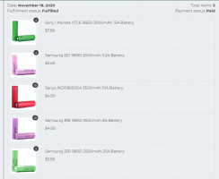
@Bubba You mean like these? I believe these are ≈20mΩ. Now remember my philosophy about Sony Green cells. If they are the only cells in my build OK but not mixed in with a frankenstein pack. See my post https://secondlifestorage.com/index.php?threads/green-sony-cells-just-suck.5132/post-48096 The mistrust of the GR series does have me a bit gunshy of the VT series which may be totaly unfounded.
1610542911243.png
 
LOL yes most of my seriously marginal cells have probably been melted down or recycled in some form or another. Nevertheless I just remembered I still have a some medical, laptop, and power tool packs I haven't opened yet. I want to put cells through the tester that we would likely use. I mean a Sanyo with 700mAh is a good representation of a bad cell but we wouldn't put that in our powerwalls. At least I wouldn't. So I am on the hunt for that marginal cell we would consider using but probably shouldn't.
IR my friend is the truth detector whether you use a AC IR meter to determine its SOH or a stress test by a C/D/C 1 Amp cycle you cannot avoid the effect it has on a cells performance. I now also feel that it should be considered a safety check before commiting a cell to a powerwall build. Especially if there is more than a 500mA draw on the individual cell. Additionally as my parallel test have shown just because you draw 4A from a set of 4 parallel cells does not mean all cells will give you 1A each. If they are reasonably matched then yes the Amp draw on each cell will be similar. But if you have severely mismatched cells some cells will give way over the calculated 1A draw. Soon enough we will get into a more realistic scenario of whole pack draw of 250mA per cell. I dont on the other hand foresee a much different scenario. I believe the imbalance will show more stress on certain cells i.e. some cells will discharge at 100mA and others at 600mA. We will see.
@Bubba You mean like these? I believe these are ≈20mΩ. Now remember my philosophy about Sony Green cells. If they are the only cells in my build OK but not mixed in with a frankenstein pack. See my post https://secondlifestorage.com/index.php?threads/green-sony-cells-just-suck.5132/post-48096 The mistrust of the GR series does have me a bit gunshy of the VT series which may be totaly unfounded.
View attachment 23377
Are these the same chemistry?

I do find interesting these cells were never sold to the public. They were for pack design only and a limited run. At least that Is what I read at one point. I was hoping to see the reaction between cells with such low IR and high IR... make things obvious. :)
 
Are these the same chemistry?

I do find interesting these cells were never sold to the public. They were for pack design only and a limited run. At least that Is what I read at one point. I was hoping to see the reaction between cells with such low IR and high IR... make things obvious. :)
I believe the Sony/Murata VT4 cells are NMC (Nickel Manganese Cobalt) hence the low IR.
Hm I did buy them from a retailer though so they are "new" . I may have some used ones from power tool packs. I'll look.
If you want a reaction between high and low IR just look at the second test I did https://secondlifestorage.com/index...r-of-cells-in-parallel-take-2.8857/post-71436 Pretty ovious difference between ICR and INR chemistry anyway.
Could I get the Coles Notes? Sorry my brain is a bit scrambled

Not seeing the obvious. Would like to see low amp draw and high amp draws. Running the cells from full charge to cuttoff.
I believe (without evidence) that mix of high draw cells with lower draw cells (various chemistries) is not as important when there are many cells and the draw is low.
 
Could I get the Coles Notes? Sorry my brain is a bit scrambled
LOL you think your brain is scrambled, you should see mine.
Right now I'm doing 1A per cell (3) C/D/C cycles.
If the cells are all the same as in all same brand, same part number, same age, and same IR the discharge curve is flat. there is no crossovers. All cells discharge at 1A. First section of the graph trace
If you have different chemistries as in INR and ICR with the same mAh capacity the cells will discharge/charge at a different rate throughout the D/C cycle. switching at times to fulfill the responsibility of the load.
The frankenstein scenario is demonstrated in the 3rd and 4th trace. All over the map. Also temperature is starting to be a factor.
Here is the 30000 ft view and the differences can be easily seen.
30000foot.png

I have a bunch of cells prepping for more frankenstein scenarios. I am looking for that combination that gives me a heater.
20210113_211104.jpg

Wolf
 
Last edited:
OK Ladies and Gentlemen.
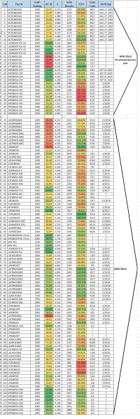
In all my "Spare" time I have come up with 120 "Frankenstein" Cells.
These cells run the gamut from new to old, varying capacities, varying SOH, high IR to low IR, ICR and INR chemistries, etc.
Here is the Cell Matrix, it can also be viewed and/or downloaded here. https://1drv.ms/x/s!AmNMFw8cEOSHiGwzqm22DAZJ5QO8?e=gj5S1b
It is also attached as a file to this post.
Birthdates of the cells have been added to the ones I could figure out and / or had a date code that I could find.
As indicated the first 32 cells are brand new and were purchased Nov 2020.
Cell Matrix.png20210203_215317.jpg1612410666911.png
So here is were you guys come into the picture,.
Pick any 4 cells and tell me what you want to do with them.
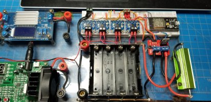
I will run them through my newly updated parallel cell tester and graph the results.
This is of course if you all are interested in the results of how cells react in parallel.
Tell me how you want to charge them as in what final voltage at what mA, at what mA per cell you want to discharge at, and to what voltage,.
I can also introduce a timed load resistor, I have 1Ω, 2Ω, and 4Ω available, in series or parallel we can get any combination you want, to discharge and rest as in 5min discharge 5 min rest. I suppose the options are only limited to your imagination and my coding skills. Also of course my time.
So help yourself I have given you 120 cells to play with ..............
Have fun

Wolf


Attachments

  • ptest.xlsx
    46.2 KB · Views: 145
Last edited:
@Oleksii
Quite interesting and certainly useful.
It certainly does a great job comparing and showing each cells models discharge curves at different amperage draws.
I suppose you could extrapolate the interaction between 2 cells from these charts.
Using my tester and actually having 2 or in my case 4 potentially different cells with different IR and mAh rating will show more of an interaction between the cells as discharge or charging happens. The individual discharge curves are all a fine and good way to attempt to match cells with similar curves but it does not show their interaction between them as the discharge occurs.
Wolf
 
Back
Top