DanJohnson

New member
Joined
Aug 24, 2021
Messages
5
Hello, I'm a first semester graduate student in the USA and I have recently gotten super interested in Lithium Batteries! I have a ton of used 18650 cell's I've harvested from all sorts of products and while I was building an E-bike battery last year I was beating my head against the wall trying to test close to 200 cells using an OPUS BTC3100 and waiting hours to test 4 cells at a time. This gave me the idea to dedicate my research to finding a way to create a faster way to test used 18650 cells quickly and accurately without having 20 testers on a giant power supply and still spending hours at a time.
I was originally going to try and develop an internal resistance tester that uses electrochemical impedance spectroscopy (EIS) to instantly determine Internal resistance and save you the time of running charge discharge tests, but then I realized that was going to require a lot of expensive equipment that I most likely wouldn't be able to afford with my $1500 budget. I also just found this site and due to the amount of very knowledgeable and experienced professionals and hobbyists on here I figured y'all might have some ideas.
My goal is to find ways to make it easier for people to quicker way other than charge/discharge capacitance tests to accurately determine if a used 18650 cell is worth keeping or recycling. I see a huge amount of waste from used 18650 cells that still have a long usable second life, but due to difficulty in testing they are thrown out or collected by "recycling" companies but ultimately ending up in the landfill.
I would love to hear any input from this community about possible technologies to investigate, ideas for tools that would make testing used cells easier, gaps in the community knowledge that could benefit from formal research or really any suggestions.

I look forward to hearing from you all and I'm excited to have finally found the community I've been looking for!

Best,

Dan
 
Try this

I don't think you need expensive kit, check Wolfs threads of cell testing, experiences and how he has tested cells with a smart approach.

For short duration minimal test time, highly accurate kit, however, extend the time and you compensate for the measurement accuracy.

For cycle degredation high accuracy energy in/out is needed if you only want to measure with a few cycles. Time is what you have and just parallel up.
 
Battery University has been out there for a long time... but I actually based some of my key design decision on the long life page. If you haven't see it you might check it out for some tid-bits - https://batteryuniversity.com/ and in particular I've used this one for my operating guidance - https://batteryuniversity.com/article/bu-808-how-to-prolong-lithium-based-batteries

Today I'm an 1,068 daily cycles at avg 40% DOD on my oldest 18650 battery in my DIY powerwall with no detectable loss of capability yet.
 
Welcome to you researcher! :giggle:

Well, testing cell capacity via C-D-C cycle is a very practical way of finding actual cell capacity.

I'm pretty sure that a high-technology density/chemistry analysis of a cell is somehow possible, but that's surely not available at low cost.

For what concerns your goal of obtaining an accurate measurement I can tell you this: I've just finished measuring 1046 cells for a total of 7934KWh, using three Liitokala 500 chargers, testing about 36 cells/day. More than once I really desired having ten chargers which would bring my numbers up to 120 cells/day which would be quite fast.

Consider that talking about second hand cells it's advisable to go through a 10/15 day test for each cell, following a strict procedure that will help getting a quality set of cells. Quite a good protocol is described in this thread: https://secondlifestorage.com/index.php?threads/18650-harvesting-flow-charts.9714/#post-66506.

Getting a really accurate measurement is not possible unless your testing procedure is aware of both cell datasheet and load you will connect to the cells.

For example, look at datasheet for Panasonic/NCR CGR-PD cells:

Panasonic PD discharge curve.jpg

For a new cell, testing at a 0.55A discharge rate would give you a measurement of nearly 3000mAh. While testing this same cell at a 5.5A discharge rate would give you a measurement of about 2750mAh.

This is Samsung 22F datasheet:

Samsung 22F discharge.jpg
Again, testing with Liitokala 500 the measurement with discharge rate at 0.5Ah will be higher than an Opus with discharge rate set a 1.0Ah.

Now, as you surely know, when we mass test cells we ignore cell model and set the discharge rate at a fixed 1000mAh (or 500mAh rate on Liitokalas, which is the reason that Liitokala gives a higher capacity reading -as @Wolf teaches us). So when doing mass test we obtain a reasonable capacity measurement, but in real usage of that cell it's possible we can get a higher capacity out of it (or lower, depend on the load).

So, for once here in the forum we can say that Liitokala 500 measurements for an application where load is 0.5A are more precise than the numbers you get with any other faster charger set at 1.0Ah discharge rate.

Going to a faster testing method: using a higher charge/discharge rate means that each test is faster. So if you make your DIY charger which can push more amperes into cells then the test will be faster (keeping in mind the datasheet maximum rates). But, it may not make sense testing cells at their maximum ratings when your load is maybe as little as 0.5A.

[EDIT: ops sorry Korishan! I made a normal thread post out of an intro]
 
In which Voltage Range, do you keep them?
4.0v/cell high and 3.54v/cell low are the overall settings.
In Winter its in the lower portion of the operating range - 3.8v hi (on average) - 3.54v low - due to lack of sun to get it up to 4.0v.
In Spring/Summer/Fall it will more often hit 4.0v/cell hi.
The overall yearly average is 3.85v high to 3.54v low.

The overall battery bank was gradually enlarged to achieve these ranges w/respect to the home consumption patterns. I wish there was more data - for example would it be worth it to auto-adjust the range a bit higher in winter for longer life? or would it pay to double the battery bank size? Just not enough data and batteries are a bit 'variable' in their nature.
 
Last edited:
My goal is to find ways to make it easier for people to quicker way other than charge/discharge capacitance tests to accurately determine if a used 18650 cell is worth keeping or recycling
Well that was my goal also. That is why I developed the IR cheat sheet. https://docs.google.com/spreadsheet...ouid=105132588382800520118&rtpof=true&sd=true

For a reasonably accurate IR reading at that low of an ohmage it needs to be accomplished with the 4 wire kelvin methode. Also most manufacturers post the "acceptable" mΩ of a cells impedance at 1khz AC. This measurement can be accomplished with quite a few mΩ measuring devices.
I personally prefer the RC3563.
My workflow basically is liberate the cell, check Voltage and IR, as long as IR is acceptable for the specific cell part number and manufacturer, and the Voltage is reasonable the cell has a very good chance of being good.
I have got the procedure down to a science and pretty much can tell you if a cell will pass the muster or not by examining the date code, cell chemistry (ICR, INR, or Hybrid), IR and V before it even gets close to a charger/tester/analyzer for a C/D/C check.
My sheet of over 6000 cells tested with IR and mAh results has a lot of info that can be gleaned from it.


Also check out this thread.


Have fun
Wolf
 
Last edited:
Thank you everyone who contributed! I learned a lot from the links and resources you all connected me to. Wolf, big thanks to you too, your data excel sheet has been extremely valuable in helping me design my idea and I'm working on a prototype for could potentially increase the speed of your testing method that I'll share with you all when I'm done! Thanks again, you all are awesome!
 
If possible to implement, measure the IR + Voltage before testing, even if its under 2V or so and once more after its charged to 4.20v at the end.
The data could be very usefull for future reference, as i know someone who is working on a tool to guesstimate the reliability of a cell at different recovery voltages which already works well, just needs more data to be feed.
 
Looks like @Paddy72 deleted his comment, If you'd still be willing to share your info about your friends research I'd be happy to help collaborate. I'm very close to a working prototype and in the interest of opensource community resources I may be able to provide helpful information to them in exchange for a glimpse at what they've got.
Thanks again all.
 
Well well that's interesting if you want to see from where this all came from then look at the threads and posts from late 2018 where a bunch of us where contemplating the usefulness of IR measurements. This is nothing new although I applaud anyone that's willing to explore this to a proper conclusion. There may be a doctoral degree in all this.

I have already published my theories and data and have spreadsheets that definitely prove that IR has a correlation to a cells SOH.
Anyone that has read my posts will find many answers to these questions.
I do not claim to know all the answers but I have enough research under my belt to give some quality answers.

For those of you who are up to some good late night reading till your eyes gloss over consider this the beginnings of advanced cell harvesting research.
Wolf


Last edited:
Hi Wolf,
i absolutely agree Ri is an important parameter when investigating a cells SoH. Until now i did the Ri measurement manually with a classic DC-load method: Read Voc and read V(loaded) and calculate Ri using Ohms law - its quite simply. The disadvantages of this classic DC-load test over the AC (typical 1 kHz) Ri-test are obvios: if you use too low of a load resistor you will discharge the cell and the voltage drops during measurement - how long are you going to wait for a steady reading? Also the error of this method is relatively big, even when carried out with a proper 4-wire measurement due to arbitrary connection resistance (even if you do your best).
The AC-method instead is quite easy (with a YR1030 or YR1035 or alike) and much better in reproduction and accuracy. So i ordered one lately and will do my measurements again.

If you know the typical Ri of a cell under test you can quite well estimate the SoH by measuring the actual Ri. To keep data comparable you should define at which SoC (Cell rest voltage) and what temperature you do the measurement, as both parameters will influence the Ri. A mistake imho is to measure the Ri directly after a full charge. All cells tend to drop quite a bit in voltage directly after full charge, some more, some less - but this is not an indication of SoH. So its better to test at a stable rest voltage, where you normally would store your cells - so near 50% SoC, i.e. around 3.8...3.7 V.
 
@paddy72
Very good writeup. I myself built an arduino 4 wire DC IR tester with an INA260 and ADS1115 timed the test cycle with an MOS.
Wrote some code to make sense of all the data and Ohms law R=V/I to find the internal resistance of the cell.
SInce the ohmic value that we are measuring is so low a 4 wire holder with good tension is a must for repetitive results that can be trusted.

1637378206997.png
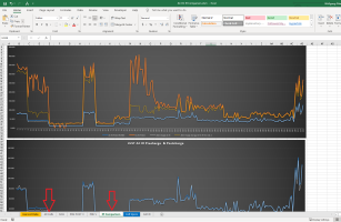
Then used PLX-DAQ to gather the data into excel to be able to draw some interesting charts.
If you want to see my study on DC IR download the spreadsheet that has 226 cells recorded as they were pulled from their packs and DC IR and AC IR was measured as the first measure no matter what Voltage. Temperature was always between 20°C and 25°C and the difference showed little if any deviation.
I was able to find 2 cell spec sheets that actually have DC IR listed and I just so happened to have the INR18650-30Q in my lot of tested cells.
Here is the spec sheet for the INR18650-30Q and the DC IR and AC IR specs are very close to what I came up with.
And here are my INR18650-30Q cells filtered out
1637381320835.png
Then the Cells where C/D/C and after mAh was recorded Voltage, DC IR and AC IR again checked. Some interesting results. Turns out that on a good cell DC IR is ≈2X that of AC IR. Also on a good cell you can get an acceptable IR Reading from ≈4.2v to ≈3.3v l. Below 3.3v the cell will generally not have enough umph to give a reasonable voltage drop through a low resistive load and IR will indicate in the ionosphere.
Another thing I did is after the C/D/C is measure the cell twice to see how consistent my DC IR tester was. Well you be the judge. I can tell you this much, with a good cell like the ICR18650-30Q I could perform the DC IR test 4 to 5 times in rapid succession before the DC IR started to creep up. Let the cell rest for a minute and it would be right back to its original value. So as far as consistency was concerned it was there.
The good thing about AC IR though is that it can measure the SOH of a cell with 0% SOC or 100% SOC and get very close results, weather at 100%, 50% or 0%, whereas you need to charge a cell to at least 30% SOC for a proper DC IR test.
The spreadsheet above has some neat charts that I built that are filter sensitive so you can filter the sheet by cell type voltage range etc and can get a chart for you to analyze.
1637381697053.png


Also resistive load doesn't matter that much. A 1Ω and a 4Ω resistor where used for testing and the difference was minimal.
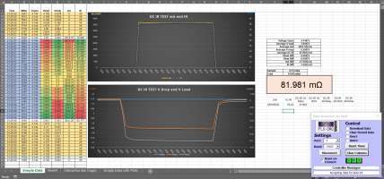
Here is a UR18650ZT Cell tested with a 1Ω resistor giving the cell a ≈3.65A current load which resulted in a 0.299V drop resulting in a DC IR result of 81.981mΩ
UR18650ZT 1Ω+Relay.PNG
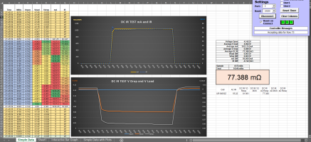
The same cell was tested with a 4Ω resistor giving the cell a ≈1A current load which resulted in a 0.08V drop resulting in a DC IR of 77.388mΩ
The difference of 4.593mΩ not bad for a cobbled together DC IR meter. Since the arduino measures current through the main wires with the INA260 and the voltage drop through the sense wires with the ADS1115, load resistance really has little to do with the results. I chose to use the 1Ω resistor for most of my testing as it gave a good indication if the cell was up for the task esp after a C/D/C. cycle. Also I settled on 1000ms as that seemed to be the best time frame to capture a relatively true representation of the cells behavior and be able to average out the mΩ results.. 500ms would also work and gave the same results as did 1500ms and 2000ms beyond that the battery would fatigue a bit and the DC IR started to become skewed.
UR18650ZT 4Ω+Relay.PNG

If you want to read the thread where all this was discussed in detail check out this tread.
Have fun
Wolf
 
Last edited:
Hi Wolf,

thanks a lot for this very detailed explanation and enormous data collection! Seems you really spent a lot of time in this investigation!
The deviation from AC IR to DC IR is quite different with a broad spectrum. In general your finding with DC IR is ≈2X that of AC IR is true in my experience, but deviation from cell type to cell type can be very huge.
In general the AC IR seems to be more reliable and with better reproduction. The difference between 2 measurements in your data is much less with the AC method over the DC method.
Conclusion for me is: for the sake of consistent data collection i would prefer the AC method. But for any calculations how the cell would behave under a real load i would prefer the DC method as this will be the situation in practice. You typically load a cell with DC, not AC :)

The other point about the relevance of testing conditions is also interesting. You found that the IR doesn't depend much on SoC and Temperature?
I searched the Web for information on relavance of SoC with IR-measurement and found contradictory information. Some say IR will increase with lower SoC, some say the opposite. In any case there seems to be a kind of sweet spot with lowest IR in the middle near 50% SoC, which should be around 3.7...3.8V on the classic Li-ion cells - so thats the point where i would prefer to measure. Probably tough it wouldn't make much difference in the readings. On the other hand the effect of temperature is clear: the higher the temp the lesser the IR and wise versa. The effect may also be in the lower %-area, but could reach up to 10% for 0 deg. to 30 deg. C - did you test that out too?

I think you data findings all went into the AI tool of Andreas, the so-called "Lili", right?
Will give it a try with my cell collection (a few hundred cells so far) - the next time i test them with the new YR1035 (waiting for delivery...).

Cheers, Paddy
 
Yes AC IR is the way to go as it is quick and easy and also relatively Independent of the SoC of the cell. As far as AC IR differences between SoC percentages if you look at the AC DC IR Comparison Sheet you will see a column Diff AC IR. It shows that most of the cells IR dropped after charging a little on some more than others. My temperature statement was meant as "room" temperature which can vary ±3°C. Certainly at higher/lower temperatures there will be an IR change but all in all I do not think it would be very drastic till you hit the extremes. For our day to day measurements I think we will be OK.

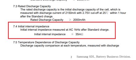
As far as the SoC is concerned for actually measuring the AC IR the manufacturer usually always state AC 1kHz after a standard charge. The spec below happens to be from a Samsung ICR18650-22P but if you get an IR spec from a manufacturer it is always after a "standard" charge.
I actually take 4 AC IR measurements on all my batteries. 1 when pulled from the pack. 2 after C/D/C 3. After ≥25 days and 4. just before the cell is committed to the pack. If you want to see that Excel Workbook https://1drv.ms/x/s!AmNMFw8cEOSHgbdvIOs6Pz4SNkIAVQ?e=aov8A7

I am not certain whether Andreas used some of my studies or not but there are some similarities.

Wolf

1637557432343.png
 
Last edited:
Back
Top