Communication between BYD Battery and Kostal Plenticore Inverter

Hi Solar Guppy,

that a good info.

So, if Battery want to do calibration it tells inverter to stop charging first. That means there should be status change in cyclic data from battery and also when it want to start calibration it send again different flag.

Unfortunately I don't have battery so I can only waiting @huntworker for that process log, it could be both x2 and x3 frames.

Btw, how the calibration calculate and who do this calculation, the inverter or battery?
Calculation is done by the battery, the inverter has no part in it except to stop charging the battery. One thing to note, the discharge isn't a controlled value, just dependent on the inverter loads and the C rate ( load over time ). I assume BYD has characterized to accommodate this, but in the end it is still a guess as it's about chemistry, not something that can be physically measured.
 
I also read on manual that the inverter could ask battery to do battery capacity calibration, it should send 63/E3 frame but to catch this you need to make longtherm logging with filtering only for that both second byte or force manually from battery website
Would be intersting to trigger the soc calibration in the battery and see what the battery is talking to the inverter.

All the inverter does is stop any charging, nothing else. Once the SOC gets somewhere below 10% the battery will responding with the calibration flag set and the inverter then starts charging the battery depending on the inverters option ( charge from grid enabled or solar energy available ).
But how will the battery get to 10% if there is no discharging from inverter? By self discharge?

Btw, how the calibration calculate and who do this calculation, the inverter or battery?
Battery is calculation soc.

I attached some logfiles. I do not want to have the battery in a low soc during winter and ther is a high battery drain even if the inverter is in off state, so I switch the battery off in the evening if it is at 20%
 

Attachments

  • 2021-12-28_full.txt
    1.8 MB · Views: 80
  • 2021-12-30_full.txt
    1.3 MB · Views: 76
  • 2021-12-27_full.txt
    3 MB · Views: 86
  • 2021-12-31_full.txt
    5.8 MB · Views: 71
  • 2022-1-1_full.txt
    5.7 MB · Views: 65
  • 2022-1-2_full.txt
    5.5 MB · Views: 69
  • 2022-1-3_full.txt
    780.1 KB · Views: 78
I looked all log, decode the zero bytes and write only last bytes beginning from cycle count.
On normal run there are no flag change on charge/recharge, only at start up there are some flag change.

Code:
starup frame:
0000 0000 14 020001 -> Max charge voltage + Nominal discharge
0000 0000 14 020000 -> + Systemp
6801 0000 14 020000 -> + Cycle count
6801 0000 14 020000 -> + pack voltage
6801 0100 14 020000 -> + cell voltage + cell temperature
6801 0100 13 000000 -> few frame after
6801 0100 13 000000 -> + charging current

other known frame:
FE00 0140 64 000000 -> full charged
0001 0100 50 000000 -> 256 cycle count

My guess:
last byte indicate first long frame
02 after SoC -> precharge?
01 after cycle-count -> ready?

On My Piko manual the battery could be in status:
Normal (Charge/Discharge), Charge/no-discharge and no-charge/no-discharge

I will play sending different flag to see if there are flag for stop charging or discharging but I need to make a small circuit first.

SoC calibration still interesting to see which flag corresponding with it.

I saw on a picture that I found in internet that there is no precharge resistor on board and precharge seems only do be pwm-controlled stage mosfet (2 of it). @huntworker could you confirm it? It should ne a fast mosfet. What mosfet are they use?
 

Attachments

  • 2021-12-27_full_striped_last.txt
    282.8 KB · Views: 75
hello,
has anyone tried to connect their own battery pack to the BYD BMU?

Greetings Stephan
 
Hi Stephan,
I dont have any BYD BMU/Battery and just have old Piko BA inverter.
BYD use Texas Instrument BQ76PL455 battery monitor chip that UART differential link that daisychainable.

Do you have BYD device? How is your configuration?
Maybe you can provide us also communication logs to inverter like @huntworker did. And also battery modul communication logs.
 
Unfortunately, I don't have any battery storage, but I would like to connect 4 x 16 LiFePo4 batteries in series and operate them on the BYD BCU.
 
I saw on a picture that I found in internet that there is no precharge resistor on board and precharge seems only do be pwm-controlled stage mosfet (2 of it). @huntworker could you confirm it? It should ne a fast mosfet. What mosfet are they use?
Thats a point I was curious as well. The precharge circuit.
I want to know how this is handeled.
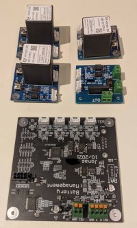
In fact I found only one relay on board (a second one can be mounted in series, but is not assembled). There are three bigger parts with cooling on it, didn't look for them in detail.
Startup process is:
  1. Switch on Battery switch by hand -> "Link voltage" (voltage between battery output and inverter input) is still low
  2. wait around 10 seconds -> relay switches on -> link voltage jumps to 252 V
  3. ~2 s later the relay switches of again -> link voltage falls down ~ 1 V/s
  4. ~5 s later the relay switches on -> link voltage stays at 252 V
  5. ~10 s later the inverter switches internally -> no change in link voltage, no discharge because battery is at minSOC.
My current guess is that they do not do any precharge because as soon as the relay switches, the voltage goes up. Couldn't do any measurements with my scope because I do not have an isolated probe. But I repeated the process several times and the delay between relay click and voltage rise is <0,3 s.
But what are they doing in step 3 when they switch off again for a few seconds?

As soon as the sun is fully down I will disconnect all wires and measure the input capacity of the inverter. Maybe the precharge is in the inverter since they are switching something internal, too.
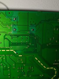
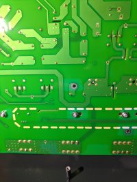
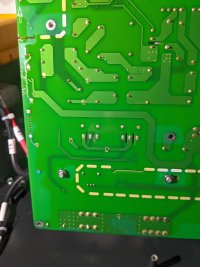
I attached a picture of the pcb, but it is in a low quality because the light is pretty bad.
EDIT: input capacity in off state is 26 µF, so in my opinion there is no precharge needed.


hello,
has anyone tried to connect their own battery pack to the BYD BMU?
Didn't even thought about this. And it doesn't make sense in my opinion to buy a BYD Battery BMU to operate with selfmade cells. The protocol is even more undocumented. And you will have mechanical issues to adapt the connectors. Only vaild point would be if you have a full BYD battery with low capacity (damaged) cell packs and you would like to replace the cells. But I guess this will be hard as well because you need to have detailed knowlege of the CMC. Not sure if the use the bare metal BQ chip or if they have a separate controller on each pack. At least each pack has its own serial number.
The serial number of the BQ is a 16 bit value while the serial number of the battery pack is in format 1C111910-xxxxx or 1C121910-xxxxx, so maybe the xxxxx is the 16 bit value from the BQ.
 

Attachments

  • image.jpg
    image.jpg
    1.4 MB · Views: 104
I haven't found any defective cell packs, if so these are always sent back to BYD.

I would like to use an HV battery on my Kostal inverter, but I would like to use my own LiFePo4 cells.

What other possibility is there?
 
What other possibility is there?
Same thing what I am doing: build your own BMU :)
I will do an own thread for this as soon as something is working. Plan was to do the first live test end of last year but it didn't took place yet...
 

Attachments

  • PXL_20220205_184815966.jpg
    PXL_20220205_184815966.jpg
    534.6 KB · Views: 120
  • PXL_20220205_184800980.jpg
    PXL_20220205_184800980.jpg
    811.7 KB · Views: 113
  • PXL_20220205_184734290.jpg
    PXL_20220205_184734290.jpg
    463.9 KB · Views: 121
Nearly forgot about the SOC calibration test I did today:
Attached the log.
It startet a few seconds (maybe a minute) befor the calibration.
There was no big effect, no charge from grid, no other message.

Then I clicked on restore SOC calibration and the only effect was that the soc changed from 20% to 17%.

Not sure if this is because the sun was already down (the inverter was active with 21 W from PV but no AC production).

Maybe you can see something in the log. I will analyze it as well and will tell you if I found something interesting.
 

Attachments

  • 2022-2-5_full.txt
    96 KB · Views: 79
Last edited:
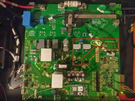
About precharge, my Piko BA or all inverter has electronic switch to disconnect modul/battery strings and it has electronic precharge witt IGBT. I think BYD has also precharge, see marking on pic.

What battery monitoring chip do you use for your DIY BMS? I saw some chip from infeneon and ST that has build in SoC and SoH monitoring. But you are right may be better to talk about hardware in different thread.

Quick manually looked your log. I saw no flag chengement, maybe I overlooked some byte.

addition1: @huntworker could you make clear picture to MCU module?
addition2: no flag changed in log (attached)
 

Attachments

  • image_marked.jpg
    image_marked.jpg
    434.2 KB · Views: 83
  • 2022-2-5_full_soc-cal_striped_last.txt
    8.8 KB · Views: 62
Last edited:
About precharge, my Piko BA or all inverter has electronic switch to disconnect modul/battery strings and it has electronic precharge witt IGBT. I think BYD has also precharge, see marking on pic.
But if the inverter has precharge internally, ehy should I need it in the battery as well?
This won't work because there is no capacitance in the inverter to precharge, as you said, the inverter switched off its port.

@huntworker could you make clear picture to MCU module?
sure, I will disassemble the PCB and will make pictures from both sides with better light conditions. Maybe this evening or tomorrow. Today we finally have a sunny day and I want to use it to charge the battery. :)

What battery monitoring chip do you use for your DIY BMS? I saw some chip from infeneon and ST that has build in SoC and SoH monitoring.
I am not using a special battery chip. It is an Cortex M4 Chip like the STM32F4 series, but it is from NXP because I am from the automotive industry and they are widely used there and I had some of them here. :) SoC calculation is not that mandatory for me, steps in 10% are fully okay for me.
 
But if the inverter has precharge internally, ehy should I need it in the battery as well?
It is better to have it also in battery. What happen if the inverter already in ON mode before battery voltage switched ON? My inverter has 30mF after its relay.
If you monitor link voltage you can make precharge time faster or PWM duty-cycle higher depend on that voltage.
I am not using a special battery chip. It is an Cortex M4 Chip like the STM32F4 series, but it is from NXP because I am from the automotive industry and they are widely used there and I had some of them here. :) SoC calculation is not that mandatory for me, steps in 10% are fully okay for me.
How you manage cells balancing?
 
It is better to have it also in battery. What happen if the inverter already in ON mode before battery voltage switched ON? My inverter has 30mF after its relay.
If you monitor link voltage you can make precharge time faster or PWM duty-cycle higher depend on that voltage
Sure it would be better to have it. And it is also implemented in the electronic, but I don't want to have it with a fet but with a relay. And I don't have another relay for 450 V and let's say 5 A. :)


How you manage cells balancing?
Each pack still has it's balancing circuit but I need to monitor each pack voltages to balance the packs.
 
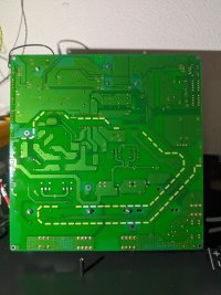
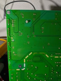
Here some photos of the BYD PCB.
The three heatsinks are connected to an Toshiba K3878 (900 V 9 A n-Ch MOSFET).
I think the left one belongs to the power supply. Together with the capacitors, the transformer and the diode and capacitors on LV side.

Some pictures are too big to upload so here is a link:
https://cloud.bardevo.de/index.php/s/oj5mpfYLi6PbEXp
 

Attachments

  • PXL_20220208_161548724.jpg
    PXL_20220208_161548724.jpg
    7.9 MB · Views: 60
  • PXL_20220208_161554497.jpg
    PXL_20220208_161554497.jpg
    7.3 MB · Views: 65
  • PXL_20220208_161558812.jpg
    PXL_20220208_161558812.jpg
    7.7 MB · Views: 65
  • PXL_20220208_161600983.jpg
    PXL_20220208_161600983.jpg
    7.6 MB · Views: 64
  • PXL_20220208_161603944.jpg
    PXL_20220208_161603944.jpg
    7.8 MB · Views: 73
  • PXL_20220208_161606282.jpg
    PXL_20220208_161606282.jpg
    8 MB · Views: 73
  • PXL_20220208_161609133.jpg
    PXL_20220208_161609133.jpg
    7.9 MB · Views: 79
Needs to be the precharge. Consists of 2 anti series mosfests with this green thing.
is it PTC? which value
There is nothing written on the part or the PCB.
It has 123 Ohms at 20 deg C.
PTC would make sense here.
 
Hi,
nice to see you interested in the topic. :)


You mean the last block, in this case 75 93 50 40? I am pretty sure that this is the voltage of the lowest cell since this matches well with the SOC.


If I have a closer look, the Header of the messages is always the same
E2 FF 02 FF 29 for messages from the battery to the inverter
62 FF 02 FF 29 for messages from the inverter to the battery
So the only change is in the first nibble. But with a even closer look you might see that it is even only changed in the first bit:
0x6 = 0b0110
0xE = 0b1110


Sure, please find the file attached.
Power off is quite easy, the communication just stops.


Edit: attachment was duplicated
Hi I found your thread when googling for BYD Modbus Spec - maybe you are already beyond that, but thought I mention https://github.com/OpenEMS/openems/blob/develop/io.openems.edge.battery.bydcommercial/doc/20200323(New)RS485%20MODBUS%20based%20communication%20protocol%20between%20BMS%20and%20%20PCS%20V2.1_20190323_.pdf

Thanks,
Reinhard
 
Hi Reinhard,
I already, saw this document, and if I am right it has been in this thread.
Unfortunately this description does not match to the measurements and logs I did.
Baudrate is matching but the header is differently, the CRC calculation is done in an other way and even the numbers are representated in an other format.
In my logs, the numbers are transfered as IEEE floats, in the linked document they are transfered in mV, mA oder 1/10 V, so as integers.
 
Back
Top