zurkeyon
Member
- Joined
- Oct 4, 2018
- Messages
- 53
Ok,
So for my Motorhome/Tinyhome Battery Build, I have a space in the understorage that rides the frame rails where I will put my battery pack.
58.8VDC Max 720ah, 4P16S pack, with matched cells from a seller I trust. All A grade, with an average of .5ah difference across x64 cells.
My budget to build this pack is limited, so for now, I need it arranged in 4P to prevent having to buy x3 additional BMS.
The cells are new, matched, and will be reconfigured to 4 individually managed 58.8v packs set up in parallel to each other, when funds allow it within 1-2 years.
In the pics, you can see my basic setup, but here are the design details so far... Just so my question coming up makes more sense.
Details:
Space in understorage is 46.5" Wide x 13" Tall x 40" Deep. The cells are 11" wide, and 16 in a row is 39" deep exactly.
The rails I have built, have a flush mounted aluminum L channel on each side, and can hold the load at 150lbs ea, and have a stop block on the back of each rail. Each rail is 41.5" long, and leaves a 1/2" indent at the front end when all cells are loaded and pushed back. Each rail will have a PVC 12 mil sheet bottom, with a PVC sheet separator mounted to the right side of each rail/mount. Cell groups are held together with Fiber Tape, Pulled tight to create a few lbs of tension, and applied with a rubber roller for max contact. The tape is also covering x2 layers, the exposed aluminum ends of each cell.
The Rails will ride the frame in the middle of the coach, and use the pictured L brackets as feet to hold onto the hump atop the frame rails, and prevent each rail from moving. Then a ratchet strap, will be fitted under the gap the feet make under each rail, and will apply the Fixture tension from the front, with a fitted 2x4 plate to equalize the pressure.
This will also keep the cells in place when the coach is in motion.
Each strap will be off center enough to see the expansion valves for regular inspection.
A 250A Daly BMS, Victron Smartshunt500, Morningstar MPPT-30, Morningstar TS-60, and 2 banks of Midnight Solar Breakers, and two 1600watt solar arrays will be charging and managing the pack in a 4p 16s Config for the time being.
NOW... On to the Question.
I am using a combination of the applied 150a Bus Bar, plated copper, and 2 AWG wire. 130a rated.
My Sigineer 6000watt Split phase 120/240 inverter/charger can pull at MAX load, 109 Amps from the pack. Which we budget our power usage and would NEVER run the inverter for long periods at beyond 75% load. So closer to 80-90 amp draw would be our typical MAX draw.
Questions are:
1. Does my use of 2AWG wire and 130 amp ampacity at 95F sound correct?
2. Is 40-50 amp overhead enough to be safe on my wire temperature if my average max draw will be 80-90a?
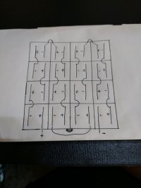
3. Is wiring the pack in the way it is on my paper diagram that is pictured, ok for now? until I can afford better custom bus bars?
I understand the left to right bonded configuration is better than the front to back flowthrough config I have on paper now. But will it work for now without harming anything? Even if it is less efficient?
I watch this pack like a hawk, and the starlink keeps me connected to it at all times. Via a tablet running at home with the daly app and the victron app that I can dial into.
I have all the proper breakers, disconnects, terminal blocks, and insulators, and I am using crimped copper lug connectors of the exact size for my laser welded battery terminals.
Let me know, based on the above, if you think my setup will work as described until I can split the packs up and afford the extra gear.
Thank you, and I apologize for the book.
Steve
So for my Motorhome/Tinyhome Battery Build, I have a space in the understorage that rides the frame rails where I will put my battery pack.
58.8VDC Max 720ah, 4P16S pack, with matched cells from a seller I trust. All A grade, with an average of .5ah difference across x64 cells.
My budget to build this pack is limited, so for now, I need it arranged in 4P to prevent having to buy x3 additional BMS.
The cells are new, matched, and will be reconfigured to 4 individually managed 58.8v packs set up in parallel to each other, when funds allow it within 1-2 years.
In the pics, you can see my basic setup, but here are the design details so far... Just so my question coming up makes more sense.
Details:
Space in understorage is 46.5" Wide x 13" Tall x 40" Deep. The cells are 11" wide, and 16 in a row is 39" deep exactly.
The rails I have built, have a flush mounted aluminum L channel on each side, and can hold the load at 150lbs ea, and have a stop block on the back of each rail. Each rail is 41.5" long, and leaves a 1/2" indent at the front end when all cells are loaded and pushed back. Each rail will have a PVC 12 mil sheet bottom, with a PVC sheet separator mounted to the right side of each rail/mount. Cell groups are held together with Fiber Tape, Pulled tight to create a few lbs of tension, and applied with a rubber roller for max contact. The tape is also covering x2 layers, the exposed aluminum ends of each cell.
The Rails will ride the frame in the middle of the coach, and use the pictured L brackets as feet to hold onto the hump atop the frame rails, and prevent each rail from moving. Then a ratchet strap, will be fitted under the gap the feet make under each rail, and will apply the Fixture tension from the front, with a fitted 2x4 plate to equalize the pressure.
This will also keep the cells in place when the coach is in motion.
Each strap will be off center enough to see the expansion valves for regular inspection.
A 250A Daly BMS, Victron Smartshunt500, Morningstar MPPT-30, Morningstar TS-60, and 2 banks of Midnight Solar Breakers, and two 1600watt solar arrays will be charging and managing the pack in a 4p 16s Config for the time being.
NOW... On to the Question.
I am using a combination of the applied 150a Bus Bar, plated copper, and 2 AWG wire. 130a rated.
My Sigineer 6000watt Split phase 120/240 inverter/charger can pull at MAX load, 109 Amps from the pack. Which we budget our power usage and would NEVER run the inverter for long periods at beyond 75% load. So closer to 80-90 amp draw would be our typical MAX draw.
Questions are:
1. Does my use of 2AWG wire and 130 amp ampacity at 95F sound correct?
2. Is 40-50 amp overhead enough to be safe on my wire temperature if my average max draw will be 80-90a?
3. Is wiring the pack in the way it is on my paper diagram that is pictured, ok for now? until I can afford better custom bus bars?
I understand the left to right bonded configuration is better than the front to back flowthrough config I have on paper now. But will it work for now without harming anything? Even if it is less efficient?
I watch this pack like a hawk, and the starlink keeps me connected to it at all times. Via a tablet running at home with the daly app and the victron app that I can dial into.
I have all the proper breakers, disconnects, terminal blocks, and insulators, and I am using crimped copper lug connectors of the exact size for my laser welded battery terminals.
Let me know, based on the above, if you think my setup will work as described until I can split the packs up and afford the extra gear.
Thank you, and I apologize for the book.
Steve