A step by step adventure of building the diyBMS by Stuart Pittaway.

Wolf

Moderator
Joined
Sep 25, 2018
Messages
2,009
I am going to attempt to explain every step in the best details that I can on how to go about building the diyBMS by Stuart Pittaway.
This is not meant as a criticism or toe stepping exercise of the great videos that already have been published with the how to's, but more of my journey in building this BMS. Some videos will be linked for possible clarification, but most of it will be a picture book with text explaining the sourcing issues in a "supply" crunch world.
( i.e. ATTINY841-SSU, one of the chips necessary for this build)
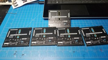
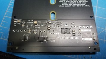
As a teaser The PCBs have all been constructed and assembled by JLCPCB with all the parts that they had in stock and received.
The controller boards (5) the shunt boards (5) and the monitor boards (75)
So stay tuned on how I did this what errors came up and collecting the information on the parts JLCPCB didn't have and how I sourced them. Getting certain parts in the US for this build is quite different than other countries. Who would have thought that?
I will share my methods and additionally when the BMS is completed any leftover parts, which there will be many as I bought from everywhere and more than I needed, will be offered at the price I paid plus shipping of course.
2 Controller boards are already spoken for, the rest stay tuned. I am not trying to make this a marketing thread so PM me with questions.
BTW if you find a shortage of ATTINY841-SSU chips in the USA market I may be partially responsible for that.:p
I hope you will find this thread interesting and please if you have any questions post them and I will do my best to explain.

Wolf

20220812_215813.jpg20220812_215820.jpg20220812_220102.jpg20220812_220123.jpg

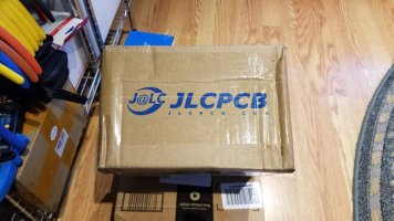
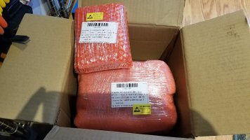
PS I felt like a drug dealer with the modules being packed 10 each and looking like a drug package.:rolleyes:

20220817_180923.jpg20220817_181009.jpg20220817_181320.jpg20220817_182030.jpg20220817_195721.jpg
 
Last edited:
I have the monitor boards, but not the controller.

The videos released are a bit all
Over the place, so looking forward to step by step instructions. I’m time poor so this will help!
 
Step Number 1 in the process of building your very own diyBMS.
Some of the instructions may be self explanatory to you and others but this step by step is written with the all time first user in mind.
I am not at present an affiliate of any of the links that I provide for you here and in the future. If that changes I will let you know.
The first thing you need to do is find yourself a PCB manufacturer, most of us will use JLCPCB as it is the easiest to use, at least that I have found.
They are very fast and the prices are quite reasonable.
Go to jlcpcb.com and create an account if you haven't done so yet.
The lower left "helpful" person popup is an annoyance but I have to admit its not a robot and the 2 times I used their help it was a rather pleasant experience and the issue was resolved in a matter of minutes. Kudos for JLCPCB support.
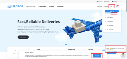
1661179447681.png
So once you have an account you are ready to dive into the world of PCB manufacturing.
Before we proceed consider the full diyBMS has 3 separate PCBs The controller, the Shunt, and the Monitor boards.
The minimum order for each PCB is 5 units so you may want to consider a group buy for the Controller and Shunt PCBs.
Let me know if you want me to coordinate this as I will be more than happy to work with all of you as time permits.

The Monitor PCBs which we will concentrate on today, are also a minimum of 5 boards no matter if you are doing a 3p 11.4 Battery (why would you?) you will need to still order 5.
So however many packs in parallel you will or have built, In my case I ordered 75. I recommend ordering at least a 20% surplus of your number just in case of human error, letting accidental smoke out etc.

OK lets get started!
I recommend you download my step by step folder which has all the files in it that you will need and I will make reference to.
Extract the folder into a location of your choosing and we are ready to begin.
Sign into your account and click on the Instant Quote button. We are going to use the latest diyBMS Module (V4.40) as our first order example.
1661180243839.png
The next window you will see is upload your Gerber file. Make sure PCB is selected it is the default but you never know.
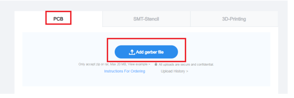
1661182268923.png
This will open a file open window and you need to navigate to the Step by Step folder you downloaded, extracted and find the modulev440_gerbers.zip file. This is the path DIY_BMS_4_ESP32 Step_by_Step\JLCPCB\ModuleV440 Files\JLCPCB_Files.
Highlight the modulev440_gerbers.zip file and click on open.
1661182741013.png

If everything worked which it should after all the internet doesn't make any mistakes you will be presented with the results.
A representation of the PCB is displayed and there is a link to Gerber viewer at the bottom but don't worry about that yet. Lets get the PCB configured and after that you can play around.
1661183220813.png
As you scroll down you are inundated with many options, the ones you are interested in are PCB Quantity, PCB Color and that's it.
Note: You may also choose 3 different HASL - Hot Air Solder Leveling methods for the surface finish. For ease of soldering the connectors I recommend the default HASL(with lead). if you are not afraid of higher soldering temperatures LeadFree HASL-RoHs is another option. ENIG-RoHS is not very suitable for us so I don't recommend it. You can always click on any of the ? marks to get an explanation.
I additionally recommend you confirm the production file adds .54 cents to the cost.
All other important settings have been imported from the Gerber file.
There is an Advanced options but as before keeping the defaults is just fine..
1661267063415.png

The next step is the PCB assembly option. I highly recommend this as the soldering and placement of some of the flea sized parts are best kept to the professionals and certainly not to the half blind and faint at heart with a soldering iron out of the sixties.

1661184220392.png
It will be bad enough having to solder or hot air whatever small parts may be out of stock at JLCPCB and in my case I would have to do that 75 times for 35 some odd parts.

Slide the "Free Assembly" button on and several options are made available.
PCBA Type will be selected at "Economic" which most of the time will be fine for a single side population of parts. As you add your parts in the next step you may be asked to switch to "Standard", if that occurs I highly recommend it. It does add to the cost but in the log run worth it.
Additionally for a small additional cost "cents", .45cents in my case, choose to Confirm Parts Placement. Agree to the terms and click confirm.
You will get a popup warning about PCB Size Requirement click OK, It will return you to the previous page and click confirm again.
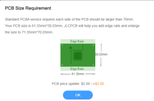
1661185784082.png
The next page is the BOM and CPL file upload. BOM (Bill of Materials) and CPL (Component placement).
Click on the Add BOM File and go to the path where you found the previous Gerber file and locate the ModuleV440_bom_jlc.csv. Click open.
Do the same with the Add CPL File and locate the ModuleV440_cpl_jlc.csv file.
1661186556965.png
Once that is complete
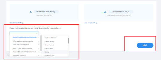
You will also need to select a usage description. I selected Sensor/Controller/Precision Instrument Battery and then click Next
1661186674396.png
Now comes the moment of truth.
How many parts does JLCPCB have and how many are missing.
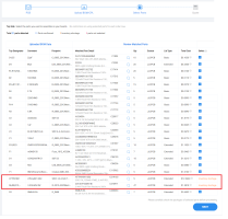
In our example we have a total of 21 parts 19 confirmed and 2 Inventory shortage.
No surprise on the ATTINY841-SSU. Unfortunately at this time the Balance resistors 3.3OHM 3/4W of which there are 9 per board are also out of stock. The Resistors SMD size is 5025 which is large enough to solder relatively easy by hand if you choose to. The only other option at this time is to wait for this part to be back in stock and then continue with the order. However we will continue this lesson for now.
Note: JST and Pin Header Connectors are not part of this BOM. Sourcing those will be explained later. Yes you will have to solder those.

Going through the parts you will have some options. By clicking on the Magnifying glass on the parts matrix it will open up choices and sometimes pictures and spec data for replacement parts but this is more for reference and I would suggest leaving it alone. You will also note that in some cases the parts count is high. This is due to "spillage/ attrition" and a minimum order quantity. Attrition is due to losing parts when changing/loading the carrier on a PnP machine and YOU will pay for them. When you are done playing click Next
1661188580066.png
You have arrived at the final stage of the Module build.
This is a preliminary representation of the board and parts and it is for reference only. JLCPCB will place the parts and check to make sure they are properly aligned and polarity sensitive devices are placed correctly. There are several options you can explore, Price and the BOM once again.
Click on Save to Cart.
1661189838499.png
From there its just a matter of going to your shopping cart and secure checkout.
One thing to remember, and this is a mistake I made, I was all excited about ordering the Shunt board and went all the way to checkout and payed. Unfortunately I was not done ordering yet and ended up with a split order and shipping. So I ended up paying for separate shipping.

1661189981598.png

You now should have your PCBs in your account file manager and order history here is mine.
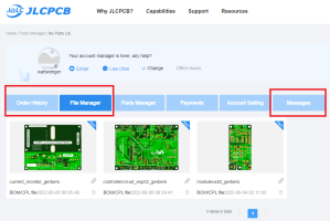
1661190406276.png

At this time you are waiting for about 4 to 6 hours and you will have things populate in your account in the Order history.
You will want to check your email and or check the messages or log into JLCPCB on a regular basis as there may be messages regarding something may not be right or there is an additional charge who knows.
It is important to answer these questions and or approvals as soon as possible especially the parts placement so not to slow down the flow of production. I trust them to know where to put the parts and so far all is ok and I have not been disappointed.
Looking at the Order History you will find several items to click on. Product details, Production time schedule. The checkmark, you see, which in my case shows completed but on a new order will have a circle showing percentage of progress.

1661191472417.png
One important option is the DFM Analysis. This will show that you have confirmed the parts placement and you can study it in detail.
I recommend it just to get familiar with what you are building.
1661191609344.png
Well that finishes up the Step by Step JLCPCB ordering process for the Modules. The Controller is quite the same whereas the Shunt is a 2 side populated board and is just a bit different. We will tackle that process in another post in the near future.
Next post will be sourcing and getting parts for the Module. In this case, because we had resistors missing, we will tackle that, the JST, pin connectors, and of course the infamous ATtiny841-SSU.
Hope you enjoyed this read and let me know if you have any questions.

Wolf
 
Last edited:
Unfortunately I was not done ordering yet and ended up with a split order and shipping. So I ended up paying for separate shipping.
Provided it has not yet shipped, you should be able to add new items to an existing order and checkout again and everything will be despatched in one shipment. I did that once in the past, so assume that is still an available option.

Nice write up.
 
Provided it has not yet shipped, you should be able to add new items
You are correct! Unfortunately I found that feature a little too late, so I recommend to plan your purchase ahead, and don't hit the pay button till all your "eggs" are in the basket so to speak.:)

Wolf
 
Step Number 2 in the process of building your very own diyBMS.
Before we get into sourcing the missing parts we are going to discover some of the whiz-bang features of the JLCPCB site that actually will assist us in finding the right parts from another supplier.
Additionally we are going to explore some of the support files that Stuart Pittaway has so graciously shared with us and are located in the step by step folder I recommended that you download.
So lets get started!
Logging into your JLCPCB account and going into the File Manager you should see your Module PCB Click on it.
This should bring you to the Select Parts page.
1661274659832.png1661274945510.png
In some instances it wont take you straight to this page and that is usually if the parts supply at JLCPCB has changed and they will need to reload your uploaded BOM. All you need to do is select the correct usage description again and hit next.
1661275385881.png
With the reloaded BOM we see that the Resistor and ATTINY841-SSU are still out of stock/or quaintly called inventory shortage.:rolleyes:
1661275649703.png
By selecting the Matched Part Detail column a drop down window gives you more detail about the part.
The Package is the important part and in this case it is a 2010 in or 5025mm which is the size description.
We also see is value is 3.3Ω 3/4 W. The only thing we are missing here is the tolerance.
1661276785397.png1661278743329.png

Hovering over the Gray print will give you a flyout of the total part description.
This is the easy way to find the exact values for this particular part but not all parts will give you that option.
Let us do it the harder way just to show an example of how to find and verify the exact part we need.
Stuarts support files help us here.
Go to the step by step file location \DIY_BMS_4_ESP32 Step_by_Step\JLCPCB\ModuleV440 Files\Support Files
and you will find the schematic.pdf. Open it and you will find the description of the resistors that Stuart had in mind.
1661277877786.png1661277980277.png


So we are on the hunt for a 5025 3.3Ω 3/4W Thick Film Resistors 200V ±1%.
A G:oops::oops:gle search of 5025 3.3ohm 3/4w 1% brings up a bunch of results. I am partial to Mouser as I have an account with them and they supply quality parts at a reasonable price.
A drill down of the part specs come up with 1 stocked item here.
Buy however many you need and pay, remember 9 per board.
This brings me to 2 other Stuarts support files. One is an interactive Parts placement webpage
ModuleV440-ibom.html - Shortcut located at \DIY_BMS_4_ESP32 Step_by_Step\JLCPCB\ModuleV440 Files
and the other is ModuleV440-bom.html \DIY_BMS_4_ESP32 Step_by_Step\JLCPCB\ModuleV440 Files\Support Files
They are neat little additions and you should explore them.
1661276899601.png
Then we have the ATTY841-SSU
I warn you getting your feet wet in the semiconductor sewers will get you permanently scarred better leave it to the professionals as this IS a cut-throat business.
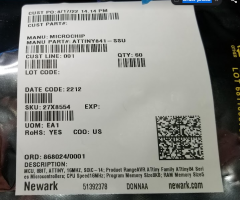
Newark is a huge semiconductor supply house and one of the few that showed stock. So I ordered 100 pieces at USD 1.25 great. Right?
1661281211653.png
Not so much. I get an email back
Hi,
Thank you for your recent order. Unfortunately, part number 27X8554 has sale restrictions and cannot be sold to you at this time. Please contact us at 800-463-9275 at your earliest convenience, referencing quote number 040396362, if you would like us to process the remaining items on your order. We apologize for the inconvenience.
Thank you for choosing Newark

Sudhir s
SALE RESTRICTIONS?
You got to be kidding me. To make a long story short I asked can you ship to Austria? Oh yea, we can do that, was the answer, so my mother will receive them and then with some chocolate bars ship them to me.
I did buy all of the Arrow stock they have 2 left.:p
AliExpress has them for USD 2.6586
Amazon has them for USD 4.1298 if you want expedited shipping.
All in all this IC is not that hard to find as long as you are willing to pay the price. I have ordered 285 all together from various suppliers.
The average cost being USD 2.8205
I paid as little as 1.4988 to the most of 4.1298 with shipping included.
I will have some left over of course and will be willing to part with some of them after I have proven them to be satisfactory.
I am also stepping into the grand semiconductor sewer Alibaba and that place is swimming with dragons and sharks. Wish me luck.

I hope you enjoyed this post and as always if you have questions please ask and i will do my best in answering them.

Wolf
 
Last edited:
Slightly off topic but it is my tread and I just needed to share this revelation with you.
Continuing the Semiconductor Sewer Saga.
Remember I ordered 100 ATTINY841-SSU chips from Newark? However there was a delivery restriction and I ended up sending them to Austria.
Well my Amazon order of 60 units came in and guess what they came in a Newark box!
They where drop shipped directly from Newark
What a Sewer this is.............
Wolf
1661359674692.png1661355968221.png
 
Since we can get the ATTINY841-SSU chips at various prices and I showed you how to source the missing 3.3Ω resistors there are 2 more items.
Sorcing parts.png
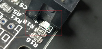
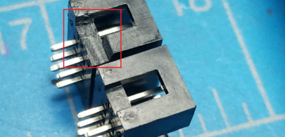
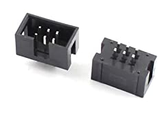
The JST connectors and the programing header. For the programing header, I choose to use the 2x3 6 Pin 2.54mm Pitch Straight Pin IDC Box Header, the black little square connector since it is keyed so when programing the module you can't make a mistake and hook the cable up wrong. One problem that the connecter causes is it covers and interferes with the blue LED ( I did break the flea sized thing but I also replaced it ) so I cut a notch out of the connector to give the LED clearance and it works perfectly.
1661632883080.png1661632975283.png
This picture is getting ahead a bit but as you see with this cable and the indexed connectors no guessing which one is pin 1.

1661633146733.png
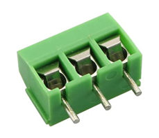
The JST connectors you can order at Newark (No sales restriction on that item ) They got almost a million in stock
The Black headers I got at Amazon https://www.amazon.com/dp/B00UBWKQLA?psc=1&ref=ppx_yo2ov_dt_b_product_details

Now this is a first for me and I did a video on how I solder the ATTINY841-SSU onto the Module board..
You can view it here.
View: https://youtu.be/2jHpaEnpQec


For those that don't want to do this PM me and I will be more than happy to do it for you, buy me a coffee someday.
I can knock out 14 in a half hour or so.

Alright that's it for the modules next the controller. Stay tuned.

Wolf
 
Last edited:
My next post on building the controller is in the works.

However my adventure of building the diyBMS is almost complete just waiting on the INA228AIDGSR current sensor chip.
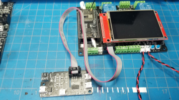
So what do you do when you have way too many diyBMS parts.
You build a mockup of a 1p14s battery. with current shunt. That way you can test the parameter out. I have also included an ABB shunt trip breaker so I can test relay and rule functions. Create different scenarios and see what happens. Also I will be able to mimic unbalanced packs by using cell with different IR, and capacity and since we already studied how cells behave in parallel we can now study how cells behave in series.
So here is the board still have some finish work to do but the controller and modules are fully functional. This BMS is cool I think we have a Batrium killer here.
Wolf
1661748633711.png
 
Last edited:
Next step lets work on the controller.
By now you should be familiar with JLCPCB and how to upload the Gerber, BOM, and CPL files and tick the proper options when ordering PCPs.
Let me know if you have any particular questions. I am also continually updating the DIY_BMS_4_ESP32 Step_by_Step folder that you can download at any time. https://1drv.ms/f/s!AmNMFw8cEOSHg-hM_dPjt_YxC35Wdg
If you are lucky when ordering the controller boards all the parts will be available, in my case, all I was missing was the RGB Led which I sourced through eBay.
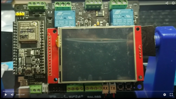
There are a bunch of things you will need to install on the board to get it ready for production.
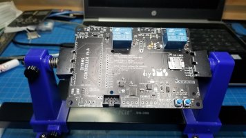
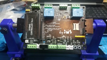
Blank and populated board
bare_board.jpg20220824_222546.jpg

Ready for testing
1662037625603.png
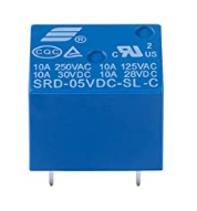
Here is the list of items you will need and where to source them. You of course can try to find them however you would like
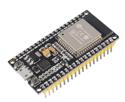
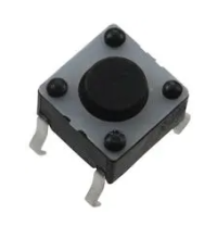
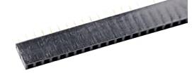
.1662036819955.png 1662036486227.png |1662036945520.png 1662037081120.png 1662037242938.png2P Can be stitched to 4P https://www.aliexpress.com/item/2255799852154488.html?spm=a2g0o.order_list.0.0.33451802yTS8tw
1662037879499.png 1662038122477.pngMany styles to choose from.
1662038247713.png 1662038409145.png 1662038531619.png or from AliExpress https://www.aliexpress.com/item/2255800444825536.html?spm=a2g0o.order_list.0.0.254f1802p6XPmC
1662040496217.png Highly recommended for backup https://www.amazon.com/gp/product/B06XYHN68L/ref=ppx_yo_dt_b_search_asin_title?ie=UTF8&psc=1

That should do it.
Next post will be uploading the ESP32 Board Test Code onto the ESP32 and running the code after building the controller PCB.
Stay tuned
Wolf
 
Wolf where did you get the solder board holder ? And when are you going to test this on a battery pack . Are you going to do a head to head with diybms vs batrium
 
Wolf where did you get the solder board holder ?
Google Pro's Kit SN-390 lots of vendors carry it from $20 to $35 just make sure its not an imitation.

And when are you going to test this on a battery pack . Are you going to do a head to head with diybms vs batrium
I don't know when yet. As you can see by the test board above I am in the stages of putting this all together. Once I have all the parts functional I will run some scenarios and go from there.

Wolf
 
For anyone in the US who’s been looking for the ATTINY841-SSU, Digikey just had a restock today. I looked 12 hours ago and the website said expected restock was in 2023 but they now have 16,410 in stock.

I’m not intending to jack this thread and I’ll start my own when the time comes. Once I’ve got my two controller boards up and running I’ll be letting go of the other 3 I ordered from JLC. I’ll include all connectors, relays, headers, esp32, and U3 which was out of stock when I ordered. Boards will not be populated and no modules will be available.
 
Thanks for the headsup on Digikey restock of the ATTINY841-SSU. Ordered some.
later floyd
 
Awesome, thanks. I think I am going to go ahead and order the ATTINY841 chips needed for 50 or so modules.

Unfortunately, the 10kOhm thermistor is now out of stock at JLCPCB -- that's the only other item they don't have at the moment! It's an awfully small piece, and at 4 per module, it's a whole lot of soldering for a guy with my skill level. (I haven't looked for it extensively, but since I already had Digikey up, they are out of stock on the thermistor as well. Newark is also out of stock of the thermistor.)

I believe I will delay my PCB order until I can get everything populated other than the ATTINY841.

Cheers, John
 
Last edited:
Have you checked to see if there is an alternative part available? If not just give it a week or so and they may be back in stock. That’s what happened to me but it was the balance resistors that were out of stock and I didn’t want to spend the time hand soldering 9 resistors on each module.
 
Awesome, thanks. I think I am going to go ahead and order the ATTINY841 chips needed for 50 or so modules.

Unfortunately, the 10kOhm thermistor is now out of stock at JLCPCB -- that's the only other item they don't have at the moment! It's an awfully small piece, and at 4 per module, it's a whole lot of soldering for a guy with my skill level. (I haven't looked for it extensively, but since I already had Digikey up, they are out of stock on the thermistor as well. Newark is also out of stock of the thermistor.)

I believe I will delay my PCB order until I can get everything populated other than the ATTINY841.

Cheers, John
Thermistors are also dime a dozen so there might be an alternative part that is in stock and would swap without causing software issues.
 
So I got my ATTINY841-SSU chips in on Friday and have been messing around with them all day. I think I've ran into some bad ones. I ordered 10 modules because the first project with this BMS is only going to be a 7S pack. I populated all 10 modules, pulling from the tube one chip at a time. I programmed every one of the modules no problem. Only 3 came to life and worked correctly. One would sometimes work and communicate but would give cell high voltage within a minute of booting. So I started replacing chips. I pulled from the same side of the tube and the next two chips rather failed to boot after programming, would not program a second time throwing failure code 3, would fail to sync with the other modules, or would start the boot process and then poof, gone, and wouldn't come back to life. So I started replacing these little bastards again but from the other side of the tube. First two programmed perfectly, sync, give accurate voltage ad temp readings.

So I'm coming to the conclusion that I've got some bad chips or they were handled improperly by Digikey or myself. So I guess a word of caution in handling and the validity of good product from Digikey's supplier or whatever.

Well crap! While typing this I had a module stop working and won't boot up. WTF!!
 
kc0dws - hate to hear about your chip problems, on many levels. I think I ordered 100 of the ATTINY841-SSU chips from Digikey last week, and it shows that they have shipped (not yet received). It may be a little bit before I get to the project, but I will update.

I also took your advice and "checked back" on JLCPCB a couple of times. I got lucky at the end of last week, when (other than the ATTINY) they had every component in stock for both the modules and the controller board. So I've got five controllers and 75 modules in production now. I assume it will be at least a week or two before they arrive. Unfortunately, JLCPCB was still missing all manner of items for the shunt board, so I have not ordered any of those yet. I forget what they were in particular, but it was at least 4-5 separate components, some with multiples per board, and some being much smaller than I wanted to trust myself to solder. That will just have to wait! (Maybe I missed it, but was there a post about the shunt board? I think it has to be assembled on the bottom, or maybe both sides? I'm working from memory, so I'll wait for Wolf's expertise!)

I did have one "error" that they e-mailed me about: requiring confirmation that the slots milled in the modules could be 1mm, which is JLCPCB's smallest tooling size. I'm not sure what the spec was for the slots, but on the confirmation drawing it didn't look like a problem. Also, the component assembly placement tool barely worked for me at all, across multiple browser platforms -- it looked like the components were all laid out adjacent to the PCB, rather than on it in the appropriate locations. This was particularly true for the modules, which never looked right; I think I once got the controller to appear with components in the right places. The online help chat admitted that the graphical layout tool is often dodgy, and the confirmation layouts all looked fine, so I went ahead and confirmed for production.

To avoid cluttering Wolf's great thread, when I get started in earnest I will probably start a parallel thread showing a noob following Wolf's instructions and tips.

Cheers, John
 
I did have one "error" that they e-mailed me about: requiring confirmation that the slots milled in the modules could be 1mm, which is JLCPCB's smallest tooling size. I'm not sure what the spec was for the slots, but on the confirmation drawing it didn't look like a problem. Also, the component assembly placement tool barely worked for me at all, across multiple browser platforms -- it looked like the components were all laid out adjacent to the PCB, rather than on it in the appropriate locations. This was particularly true for the modules, which never looked right; I think I once got the controller to appear with components in the right places. The online help chat admitted that the graphical layout tool is often dodgy, and the confirmation layouts all looked fine, so I went ahead and confirmed for production.
I received the same email about the milling size and the initial component placement was as you described for me too.
I accepted their recommendations and all came through just fine.
1666652543008.png
The shunt board is a 2 sided component PCB. In my case I was missing R11 100k flea, U3 ADM2483xRW and U4 INA228
which is almost impossible to find. I secured 15 INA228 chips from Aliexpress for $315.00 2 of them worked the others where junk.
Fortunately I was able to get a refund on 5 of them as 10 of them had a return expiration. Nice job if you can get it.
I found some INA228EVM (evaluation boards very scarce) and bought them hot aired the INA228 chips off installed them on the shunt boards and they worked perfectly So I have 5 functional Shunt boards. Programing the ATTINY1614 was another challenge which I will document and show how its done. Believe me it is easier than than you think once you get the combination right.
On another note the INA229 has the same specs as the INA228 but works on a SPI interface rather than I2C so I ordered 10 of them for $4.773 each so I can see if I can rework and use it rather than the INA228 at an unatainium price. Unfortunately they are now also unavailable WT*? Nevertheless I am working on possibly reworking the code and PCB to use the INA229. We shall see.
I also orderd at least 300 ATTINY-SSU chips from various suppliers. I marked all the ones I got from Aliexpress and used a couple of them on my test board. Yea one from Aliexpress failed right away with voltage errors and 1 is still OK all the others came from Arrow and Newark and so far no failures.
I apologize for my delay in finishing this adventure documentation but sometimes there are priorities that take precedence.
I will be back at it again very soon.
Wolf
 
Back
Top