

You are using an out of date browser. It may not display this or other websites correctly.
You should upgrade or use an alternative browser.
You should upgrade or use an alternative browser.
18650 storage
- Thread starter Tex
- Start date

Korishan
Administrator
- Joined
- Jan 7, 2017
- Messages
- 7,538
Time is also a determining factor. If they are only going to be there a month or so, then probably fine. But if time frame is looking to be more like 6 months, might want to consider dropping the voltage slightly.
And definitely in a cooler location
And definitely in a cooler location
OffGridInTheCity
Moderator
- Joined
- Dec 15, 2018
- Messages
- 2,710
I store mine at 3.6v. I toss self-dischargers and then use my iCharger X8 storage option along with magnets and nickel strips to discharge 20+ cells at a time - makes quick work of bringing down a few hundred cells left over from a battery build.
From what I've read, the idea is that when you lower the voltage the chemistry in the cell becomes quiesced and doesn't damage the cathodes/anodes/internals. The 3.6v-3.9v range is believed to be a sweet spot of maximum chemical quiet. However, even lowering things to 4.0v is better than leaving it at 4.15v from comments I've read.
Note: I recently had use for a batch of 100 cells that I had stored at house temp 2+ years ago at 3.6v - and they retested OK / added them to the current battery build with full confidence.
Last edited:
I have some cells stored in the fridge at 3.7V for over 10 years and they still kept their voltage and are o.k. I agree with storing them at lowest SoC possible but without danger of deep discharge. So for me 3.7 - 3.8 V is nearly the best level for storage. I check the voltage twice a year and rarely find a cell below 3.6 when i start to recharge a bit.
italianuser
Moderator
- Joined
- Feb 25, 2020
- Messages
- 781
Must be careful not to make a hotdog with themI have some cells stored in the fridge at 3.7V for over 10 years and they still kept their voltage and are o.k. I agree with storing them at lowest SoC possible but without danger of deep discharge. So for me 3.7 - 3.8 V is nearly the best level for storage. I check the voltage twice a year and rarely find a cell below 3.6 when i start to recharge a bit.

Tex
Member
- Joined
- Jun 5, 2022
- Messages
- 36
Ok, new conundrum,
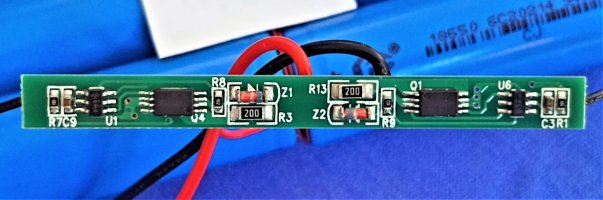
Got a few of these packs and I need to reconfigure them into 3 cells side by side, so no real big change to the BMS wiring.
But it got me to thinking, this seems a very weird way to wire up a battery BMS to me with two negative wires carrying the current.
BTW the BMs can do two batteries, I took a dead BMS and swapped the centre tap to the other pad and it worked fine. pretty sure they are cheap and nasty, ordered some replacements.
Still trying to identify the cells.
Oh! almost forgot how would I wire some balance cable for the charger in that case?
Attachments


Last edited:
Korishan
Administrator
- Joined
- Jan 7, 2017
- Messages
- 7,538
Kinda the same way you did the bms, there. You have a lead that goes between the Pos/Neg of each series group.how would I wire some balance cable for the charger in the case?
If you have 6s (with the bms connecting 2s), then you'd put a balance lead between each cell. If you have 12s, with 6 groups of 2s, then you'd put the balance leads between each 2s group. Depends on what series you're going for.
Tex
Member
- Joined
- Jun 5, 2022
- Messages
- 36
Yes I know how to do 2S but this pack is actually 1S.
My real issue now is whilst my little Accucell s60 charger is very good it can't do 1S which is what this pack is (and will be). I do like the Accucell s60 because it has a lot of capability and gives a final volt and capacity reading of a pack after charging, but it won't charge less than a 2S pack and won't work without balance leads, bummer.
My real issue now is whilst my little Accucell s60 charger is very good it can't do 1S which is what this pack is (and will be). I do like the Accucell s60 because it has a lot of capability and gives a final volt and capacity reading of a pack after charging, but it won't charge less than a 2S pack and won't work without balance leads, bummer.

Korishan
Administrator
- Joined
- Jan 7, 2017
- Messages
- 7,538
Math is correct.
is this actual battery layout, or are you just planning? It would be better if you had all the parallel cells together, and then serial them to 4s. That way only 1 bms is needed.
Or, you could take a balance lead from one pack to the next of the same group.
is this actual battery layout, or are you just planning? It would be better if you had all the parallel cells together, and then serial them to 4s. That way only 1 bms is needed.
Or, you could take a balance lead from one pack to the next of the same group.
Tex
Member
- Joined
- Jun 5, 2022
- Messages
- 36
Thanks for that.
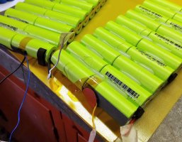
That was just my interpretation of this battery pack I was just given with new cells but a buggered BMS.
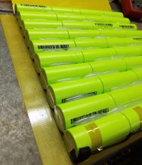
It's a big flat pack with 10P 4S and the balance lead coming off the end of the series strip (as I see it).
I don't mind keeping this format as I won't need to spot weld anything, just replace the BMS.
However, I think it was used for lighting (light load), I am a bit concerned about that little strip joining each "pack" if I put a decent load on it like my low voltage portable fridge??
That was just my interpretation of this battery pack I was just given with new cells but a buggered BMS.
It's a big flat pack with 10P 4S and the balance lead coming off the end of the series strip (as I see it).
I don't mind keeping this format as I won't need to spot weld anything, just replace the BMS.
However, I think it was used for lighting (light load), I am a bit concerned about that little strip joining each "pack" if I put a decent load on it like my low voltage portable fridge??
Attachments
-
 LiFePO4 3.2V x 10.56wWhr battery pack (3).jpg211.3 KB · Views: 36
 -
 LiFePO4 3.2V x 10.56wWhr battery pack (6).jpg217.2 KB · Views: 43
 -
 LiFePO4 3.2V x 10.56wWhr battery pack (5).jpg235.7 KB · Views: 35
 -
 LiFePO4 3.2V x 10.56wWhr battery pack (4).jpg122.9 KB · Views: 29
 -
 LiFePO4 3.2V x 10.56wWhr battery pack (2).jpg213 KB · Views: 32
 -
 LiFePO4 3.2V x 10.56wWhr battery pack (1).jpg188.5 KB · Views: 33
 -
 4S BMS (2).jpg338 KB · Views: 33
 -
 4S BMS (1).jpg304.6 KB · Views: 36
Tex
Member
- Joined
- Jun 5, 2022
- Messages
- 36
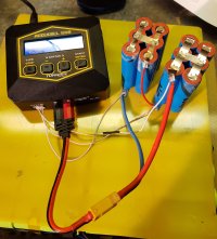
Trying this out at the moment, just trying to establish the end pack amp hour rating after charge/test cycle on the hobby charger.Kinda the same way you did the bms, there. You have a lead that goes between the Pos/Neg of each series group.
If you have 6s (with the bms connecting 2s), then you'd put a balance lead between each cell. If you have 12s, with 6 groups of 2s, then you'd put the balance leads between each 2s group. Depends on what series you're going for.
Attachments
Korishan
Administrator
- Joined
- Jan 7, 2017
- Messages
- 7,538
The nickel strip should be able to handle 5A pretty well. So putting a heavier load on them should be fine. Especially if you parallel up the packsI am a bit concerned about that little strip joining each "pack" if I put a decent load on it like my low voltage portable fridge??
What you could do considering they are already in strip packs, is to stack each of the packs together in parallel with polarities matching. Then run a nickel strip across them to tie them together. Or you could just connect all the balance leads together, which would probably be sufficient as all the packs are possibly the same age, roughly(?). This will make it so you only need one major/smarter BMS instead of using those cheap boards.I don't mind keeping this format as I won't need to spot weld anything, just replace the BMS.
Tex
Member
- Joined
- Jun 5, 2022
- Messages
- 36
Thanks.
Yes I will have a look at the possible configurations in relation to storage location, numerous possibilities.
At the moment I am struggling to find some more granular detail on these cells, I'm looking for the charge and discharge C ratings, anyone?
Code is IFR26650-33A VP17I05C31209.
Can't find anything one the Net. I have put the question to https://www.gobelpower.com/lifepo4_decoder.html but they are shut till Monday.
Attachments

Korishan
Administrator
- Joined
- Jan 7, 2017
- Messages
- 7,538
Ahhhh, they are 26650's, not 18650's. Bigger bois!
And here's their spec info: https://www.enfsolar.com/pv/storage-system-datasheet/6038
PDF: https://cdn.enfsolar.com/Product/pdf/storage_system/5ec4f93353705.pdf
Basic info:

And here's their spec info: https://www.enfsolar.com/pv/storage-system-datasheet/6038
PDF: https://cdn.enfsolar.com/Product/pdf/storage_system/5ec4f93353705.pdf
Basic info:
Tex
Member
- Joined
- Jun 5, 2022
- Messages
- 36
Hi again, so I just had an incident with one of those 26650 LiFePO4 cells, clumsy momentary short whilst reconfiguring them as you suggested, and BANG! one popped a cap.
So I figure the one that popped would be showing 0 volts, a quick check showed all cells in that strip to be correct voltage, Strange I thinks, so a close examination actually shows 3 cells with apparently blown caps (see pics) but they are all still showing correct voltage.
Question is why? and are they safe still? Ignore the black stuff, it's just torn off foam strip.
Attachments


Last edited: