Always with the questions. This time grounding.

I don't see being able to push a grounding conductor 20 feed through 4 90 degree turns
Is the conduit you laid PVC? I'm guessing so, as most installations are. However, would grounding the panels independently of the other equipment be sufficient? Meaning, drop a ground rod near the panels and attach them to it. Then have another rod at the equipment and attach the equipment to that one. I do know that there is potential difference in the wires if a grounding is too far apart. But the difference here should be very very small.
I do know on some builds where you have a barn or garage that far enough away from the house, it has it's own grounding rod. I am not sure, though, if the ground from the house is required to be bonded to the ground in the barn. With some installations, ground isn't needed as Neutral is there, and the ground is on site. However, this is all AC installations, not DC. And in some ways, they act very differently.

As far as pulling a ground wire through, you probably could try pushing a "fishing tape" through first. And then "pulling" the ground wire back through. There is no way you'll be able to push a wire through conduit that already had wires in it.
 
In windows 10 just use the "Snip" tool capture the image then go to edit and copy.
Then just paste the image into the text box and it will upload the image.
You will see the image in the text window and as an attachment.
Backspace the image out of the text window and then either insert as full or thumbnail.
Wolf
View attachment 26577
Thanks, I did try to copy and past the drawing after it was all grouped together, but it wouldn't work. I converted it to a jpeg and attached it.
Doesn't really matter at this point. I am destined to add a ground wire from array to shed to bond everything together.
 
Is the conduit you laid PVC? I'm guessing so, as most installations are. However, would grounding the panels independently of the other equipment be sufficient? Meaning, drop a ground rod near the panels and attach them to it. Then have another rod at the equipment and attach the equipment to that one. I do know that there is potential difference in the wires if a grounding is too far apart. But the difference here should be very very small.
I do know on some builds where you have a barn or garage that far enough away from the house, it has it's own grounding rod. I am not sure, though, if the ground from the house is required to be bonded to the ground in the barn. With some installations, ground isn't needed as Neutral is there, and the ground is on site. However, this is all AC installations, not DC. And in some ways, they act very differently.

As far as pulling a ground wire through, you probably could try pushing a "fishing tape" through first. And then "pulling" the ground wire back through. There is no way you'll be able to push a wire through conduit that already had wires in it.
Thanks.
Yeah, that is kinda what I have. A separate rod at the array to ground the array. Right now I have another earth ground at the shed--but I am going to have to get rid of that.
Two problems.
One is the Midnite solar combiner box bonds the DC negative to the ground (so what I thought were two isolated systems are not as isolated as I thought), and two, it seems code requires the second earth ground (DC ground) to be bonded to the home service (AC) earth ground. So will have to run the conductor.
I am going to try to run a fish through first, but with 4 90s in the run and two 4 AWG conductors already in there, I don't have a lot of hope. It is 1.25' electrical PVC, so there is plenty of room, but trying to negoiate around the turns and the wires already in there....looks like fun tomorrow.
 
If yours is to code, do you use the GFP in the Midnite solar charge controller? I am going through that with them right now, and they say if the combiner box bonds the DC negative to ground, then you can't use the GFP???
I do chassis grounding like this:
1638910390940.png
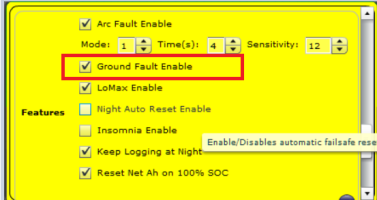
And have Ground Fault turned on...
1638910494210.png

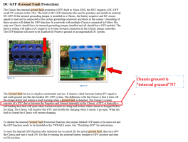
BUT, I don't have DC negative bonded to ground - not sure I need to for Midnite Classic "Ground Fault" - read below.

The electrician and city inspection seemed happy - but what did either of them know about solar/DC? I certainly don't know for sure.

1638910746857.png


I am waiting to hear back from them as to why they did that then in their combiner box.
Also, on checking, it seems as if my inverter bonds DC negative to AC earth ground??? Apparently both are no go for the GFP in the Midnite SCC.
Good gosh, I have opened a can or worms with a million heads and they all point to me being screwed!
 
Apparently, I get zero resistance between a ground rod at the solar shed, and the house ground about 80' away. This in soil that is mostly sand!!
There is however, a water table about 5 feet down, so it conducts like nobodys business.
 
I do chassis grounding like this:
View attachment 26579
And have Ground Fault turned on...
View attachment 26580

BUT, I don't have DC negative bonded to ground - not sure I need to for Midnite Classic "Ground Fault" - read below.

The electrician and city inspection seemed happy - but what did either of them know about solar/DC? I certainly don't know for sure.

View attachment 26581
Thanks, the DC negative to ground in done inside the Midnite solar as part of the GFP. but that must be the ONLY connection between DC neg and ground. I was getting zero resistance between the negative buss bar in the combiner box and the ground there (10 plus feed away).
Also, was getting zero resistance on the AC ground from the house 80 plus feet away :unsure:.
That totally messed me up.
Anyway, either way, I have to run a ground from array to shed (sigh). I will try a fish, but really do not think that will work. Heck what digging it all up again? Just a day of back breaking work. It is supposed to be good for the soul.
Just isn't so great for the mind.:cool:
 
try to run a fish through first, but with 4 90s in the run and two 4 AWG conductors already in there
get yourself the cheapest bottle of dish soap you can find, and then mix it with water of about 2:1, or 3:1 soap:water, and squirt it down the pipe as you pull the wire through. You'd need to do it several times as you pull it.
There is "electrical jelly" you could get too, but it's a little pricey, imho. The soap works really well.
And then afterwards if you want to dry the pipe back out, just hook up a shop vac to one end and let it run for about 30mins to evac the water back out. The soap will still hang around, tho.

was getting zero resistance on the AC ground from the house 80 plus feet away :unsure:.
Sound like you might have a lot of iron in your soil. that or it's very acidic. If there is no other ground connection, that's the only thing left.
However, it's possible the Midnight is grounding through itself to Neutral. Which, on the Mains side, in the main breaker panel, Neutral and Ground are bonded. So you wouldn't get much resistance reading between DC Neg and Neutral/Ground on the AC side.

It's possible the Midnight has a limiter inside that detects current flow. As long as the current is almost zero, then it leaves the pathway closed. Once current starts to flow, it throws the internal switch to disconnect; kind of like how the GFCI works.
 
get yourself the cheapest bottle of dish soap you can find, and then mix it with water of about 2:1, or 3:1 soap:water, and squirt it down the pipe as you pull the wire through. You'd need to do it several times as you pull it.
There is "electrical jelly" you could get too, but it's a little pricey, imho. The soap works really well.
And then afterwards if you want to dry the pipe back out, just hook up a shop vac to one end and let it run for about 30mins to evac the water back out. The soap will still hang around, tho.


Sound like you might have a lot of iron in your soil. that or it's very acidic. If there is no other ground connection, that's the only thing left.
However, it's possible the Midnight is grounding through itself to Neutral. Which, on the Mains side, in the main breaker panel, Neutral and Ground are bonded. So you wouldn't get much resistance reading between DC Neg and Neutral/Ground on the AC side.

It's possible the Midnight has a limiter inside that detects current flow. As long as the current is almost zero, then it leaves the pathway closed. Once current starts to flow, it throws the internal switch to disconnect; kind of like how the GFCI works.
Thanks, that is a great idea with the soap.
The DC neg to ground is part of the ground fault protection in the Midnite--I assume a shunt between DC neg and ground to with a resetting switch--like you said. But they say to make sure there is no other DC neg to ground in the system. So, I was checking for that.
When I had a ground bonded to the Midnite, this has its own ground rod about 10 feet or more away at the combiner box (which has its own ground rod), I got zero resistance between the DC neg and the ground buss bar in the combiner box (with the ground wire disconnected). The box is on one of the legs to the solar array, but those pipes only go about 3 feet into the ground with concrete.
At the inverter, I got zero resistance between the DC neg and AC neg which comes from at least a100 foot run to the house panel--the wire run was over 200 feet but was not straight and goes up and down the walls of the garage.
When I disconnected the ground wire to the Midnite solar charge controller, the resistance at those points when to OL.
The soil here is sand. but you do hit ground water about 5 feet down, and we do have iron in the water. Even though right near the beach, no real salt penetration though, but dang I did not expect that great of conduction.
 
they say to make sure there is no other DC neg to ground in the system
Yes, this is because it would defeat the ground fault protection. Breaker GFI's have the same requirement. It has to sense the ground line for leakage. If you add another bond, the leakage won't go through the shunt portion and it won't detect the current flow.

but dang I did not expect that great of conduction
This is actually a good thing, tbh. Because of this, you have a much wider area for static to build up on, which minimizes lightning strikes. Where i'm at, north-central Fl, we have loads of iron nuggets in the ground, but lower overall continuity, which means that we actually get a lot of lightning around here, more concentrated hot spots. We've lost a few well pumps because of this.

You'll always have zero, or almost zero, resistance on the DC-Neg/Ground lines through the Midnight as long as things are functioning correctly. When you'll have no continuity is when the built in GFCI throws.

But I do agree that it is interesting that you such "good" continuity across spans w/o wired connection. With that kind of soil, you might be able to make an earth battery.
 
Yes, this is because it would defeat the ground fault protection. Breaker GFI's have the same requirement. It has to sense the ground line for leakage. If you add another bond, the leakage won't go through the shunt portion and it won't detect the current flow.


This is actually a good thing, tbh. Because of this, you have a much wider area for static to build up on, which minimizes lightning strikes. Where i'm at, north-central Fl, we have loads of iron nuggets in the ground, but lower overall continuity, which means that we actually get a lot of lightning around here, more concentrated hot spots. We've lost a few well pumps because of this.

You'll always have zero, or almost zero, resistance on the DC-Neg/Ground lines through the Midnight as long as things are functioning correctly. When you'll have no continuity is when the built in GFCI throws.

But I do agree that it is interesting that you such "good" continuity across spans w/o wired connection. With that kind of soil, you might be able to make an earth battery.
Yeah, I was testing to make sure my GFCI was done correctly, and it was. It just threw me off that the ground rods had such great conductivity.
Which is great on many fronts. It means my ground system that I put in years ago for my HAM radio is functioning great.
No earth battery, this one is making me crazy as it is:ROFLMAO:
I was very concerned about using a steel fish (the only kind I have ever seen for wire pulls), might cut the pos/neg lines when trying to push it through the conduit. BUT, I checked on Amazon, and have a 40' nylon fish coming. Makes me feel much safer pushing a nylon tape through.
If I can't do it, then dig I will. Not the end of the world.
I am down to chasing just one more question, and I think I found a video that explained it. I have DC ground rod at the array, to ground everything. I will run a conductor from array to shed to connect for the GFCI system in the solar charge controller (which will have the only location of ground to DC neg). I think, I am required to bond the DC ground system to the AC ground system, so there is effectively only one ground system. I can do that at the inverter because the ground lug on it is bonded to the AC (house) ground system.
I folks are concerned about creating a ground loop, which this will, but if the rod at the array is bonded to the ground rod in the garage (well over 100 feet away), it seem to me that a strike near the array would just get dissipated at that ground rod, and any current produced to the home ground rod, would just dissipate there. So I don't think it is a problem, and I am pretty sure NEC allows that. Just not sure if it is required to bond the two grounding system together, but I think it is.
More research.
Thanks for all the help Korishan, I appreciate it.
Without this site, I would be lost and making even more mistakes than I have.
 
I think bonding the two systems my negate the GFI of the Midnight. Not sure if it will or not, but that's what I think would happen. It gives an alternative path for the leaking current to flow. This is part of the reason, a big portion really, why in AC Mains that after the main meter breaker where Neutral and Ground are bonded, they are required to not be bonded anywhere else down the line. Even with GFCI's in place, you don't bond them anywhere.
Definitely check it out for sure. Make run a few tests to verify that there isn't any leakage bypass.

For your HAM radio grounding, you probably get excellent reception due to the natural ground reflection plane :p

Without this site, I would be lost and making even more mistakes than I have.
Yeah, i've learned a lot from this community as well. A really nice collection of knowledgeable and determined individuals who seek out the answers and are willing to readily share that information, and give cautions were needed. Great bunch of ppl here for sure.
 
I think bonding the two systems my negate the GFI of the Midnight. Not sure if it will or not, but that's what I think would happen. It gives an alternative path for the leaking current to flow. This is part of the reason, a big portion really, why in AC Mains that after the main meter breaker where Neutral and Ground are bonded, they are required to not be bonded anywhere else down the line. Even with GFCI's in place, you don't bond them anywhere.
Definitely check it out for sure. Make run a few tests to verify that there isn't any leakage bypass.

For your HAM radio grounding, you probably get excellent reception due to the natural ground reflection plane :p


Yeah, i've learned a lot from this community as well. A really nice collection of knowledgeable and determined individuals who seek out the answers and are willing to readily share that information, and give cautions were needed. Great bunch of ppl here for sure.
From what they say in the Midnite manual, no where else can DC neg and ground be bonded. That was what I was checking when I was measuring resistance. It would not be, so I think that is okay.
I asked over at DIY solar, about having the two ground rods (one at the array and one at the electrical panel--over 100 feet away), both bonded together.
My thoughts were this:
If they say NEVER have two ground rods, as if lightening strikes the ground near the array, it will result in an elevate voltage, and current will flow down the ground system, through the shed to the house ground.
Fair enough, BUT, without two rods, then if lightening strikes my array (raised metal structure--more likely to get hit) then ALL of the current from the strike would travel that same path, through the shed to the house electrical ground. That sound a whole lot worse to me.
I don't think I can not bond the DC ground to the AC ground, because the inverter (when the DC neg is bonded to ground at the solar charge inverter) already puts the DC ground to the AC ground, except through the DC neg, which includes the battery. I think an alternate path would be prefered. Just don't know if NEC requires it, I think it does.
 
Fair enough, BUT, without two rods, then if lightening strikes my array (raised metal structure--more likely to get hit) then ALL of the current from the strike would travel that same path, through the shed to the house electrical ground. That sound a whole lot worse to me.
I believe this is the purpose of Lightning Arrestors (surge protectors) - e.g. to stop this. You put a Lightning Arrestor on each combined string leaving the array - and it will block surge on both + and - wires and the ground wire as well.
I used MidNite Solar MNSPD-600(s) - https://www.solar-electric.com/mnspd600.html
 
There are two ways lightning is affecting your solar installation.
The first is the direct hit into the array or supporting structure. If the mount is conductive, it is enough to use those special washers, which are placed between frame and mount and pierce the anodized coating. Then you only need to ground the mount right at the spot using a rod. Lightnings do not go around corners. Lightning doesn't actually penetrate the arrester conductor nor does its current flow inside your frames or mount. It is attracted by the ground potential and using the surface of the grounded structure to be guided to its final destination which is Earth within its own plasma channel. If you try to divert a lightning around a corner, it will get airborne again and just look for a better way to go home. That's why the best place for the grounding rod for structural grounding is right below the structure you want to protect.
But similarly dangerous is lightnings second way of affecting our installations. That is by causing surges through induction on wiring. This is what you will see on the power lines of the DC side, as well on the AC side. The surges are purely caused through magnetism cause by the high currents of lightning flowing near those wires. This induced potentials can be bled out of the system by using AC and DC side SPDs. But here as well the N-G bond in the AC panel plays an important role to provide a path to Earth. The energy induced into the system will primarily cause a high voltage spike but is of lesser current. So this SPDs etc can be connected to the house ground as well.
 
NEVER have two ground rods
Well, I think, technically, you can't have *too many* ground rods. Just as long as they are tied together properly.

So, for instance, you could have a ground rod for each major section of panels, for example every 4 panels. Then have another one at the house for the controller, and then another one for the inverter.
But this would be overkill, I would think.

There are plenty of YT videos that discuss what having multiple rods means, why you would need them, and what the problems you run into if you have too few, or too many (as in overkill).
 
Well, I think, technically, you can't have *too many* ground rods. Just as long as they are tied together properly.
Yes, there is no need to be afraid of using multiple rods, as long they are 5m/15ft away from each other. The reason is, that if you energize a ground rod due to ground leakage failure or lightning, the voltage will be gradually dissipated to zero within a radius of that distance. So if you put 2 rods close to each others, the other rod will pickup the remaining potential from the energized one. If you connect multiple rods with wiring, then you of course do not gain that isolation, but you will improve impedance. So surges will be pulled down faster.
 
Yes, there is no need to be afraid of using multiple rods, as long they are 5m/15ft away from each other. The reason is, that if you energize a ground rod due to ground leakage failure or lightning, the voltage will be gradually dissipated to zero within a radius of that distance. So if you put 2 rods close to each others, the other rod will pickup the remaining potential from the energized one. If you connect multiple rods with wiring, then you of course do not gain that isolation, but you will improve impedance. So surges will be pulled down faster.
Thanks, that is just about the distance between the rod I have a the array, and the one I have at the shed. I wanted to keep both, figuring that if I bonded the array rod to the house service ground (some 100 + feet away), that having another at the shed couldn't hurt. My current plan is to put a ground buss bar in the shed to tie everything together. Good gosh, there is so much I did not consider putting this whole thing together. What a learning experience. When I move, I will do everything different, better, the first time.
Thanks all
 
Mmm, seems (according to Penn State Solar) as if the DC neg bond at the solar inverter meets NEC code for bonding the DC to AC ground system.
Ahh, even so, I am committed (or should be committed) to running an 8 AWG line from array to shed buss bar, and bonding all the grounding together.
Going to go through what Mike Holt has to say.


Unfortunately, Mike cites a study showing that multiple grounding electrode is a bad thing.
I no longer stand by my logic that NOT having the electrode at the array makes the very situation he speaks of worse.
He makes a good point that the rod at the array would not really protect the array from a lightening strike.
Since my array is on galvanized pipe that is 3 feet in the ground, I checked, and got about 1.7 M Ohms of resistance to the ground rod only 15 or so feet away. Now that I know what is bonded to what, all that previous zero resistance readings I was getting were BS--not a surprise.
Mike has won me over.
The ground rod at the array will not protect against a lightening strike, just too much energy to be dissipated. The ground rod is ONLY for potential shorts in the system. And, having a second rod can, with a lightening strike near by, cause a problem.
I think I finally get the argument against multiple ground rods.
I am not going to watch anymore videos, I don't want to change my mind yet again--I am dizzy as it is.
 
Last edited:
Here in Australia, regs are the panel frames & rails are all bonded together & tied to the house ground.
Panels are supposed to have special washers/shims that pierce the anodizing & ground cables linking between them all (mine do).
I think it's similar in the US but not sure.
With lightning it's differential voltages that get you. Eg tree gets direct hit near panel array (assuming array on different structure to house), causes ground voltage rise near array (due to separate earth stake), house's earth stake that's further away doesn't get as much voltage rise so it's a different voltage. Now you've got a problem voltage between the solar gear & the house that blows something.
Basically my understanding is you should bond everything to a single earth point.
This is how the handout from the city to get my permit to install solar said do it. Just like you wrote. Whether it’s good or bad, right or wrong don’t matter, to get the inspector to sign off is all that matter. That 50 feet of bare copper 6 AWG still bring a tear to my eye when I think of the cost. 50 feet because no splicing allowed.
 
Here in Australia, regs are the panel frames & rails are all bonded together & tied to the house ground.
Panels are supposed to have special washers/shims that pierce the anodizing & ground cables linking between them all (mine do).
I think it's similar in the US but not sure.
With lightning it's differential voltages that get you. Eg tree gets direct hit near panel array (assuming array on different structure to house), causes ground voltage rise near array (due to separate earth stake), house's earth stake that's further away doesn't get as much voltage rise so it's a different voltage. Now you've got a problem voltage between the solar gear & the house that blows something.
Basically my understanding is you should bond everything to a single earth point.
That is pretty much the same as here in the US.
It is kinda silly that we have to pierce the insulation on the panel frames to ground the aluminum underneath--cut the insulation on the wire to ground the copper inside:LOL:
But I get the reasons.
 
Back
Top