batteryhookup nickel fuse

CrankyCoder

Member
Joined
Mar 11, 2017
Messages
95
Before there's too many comments. Yes, I have read some other posts on here. I have watched the testing videos. I saw that the fuse wire is rated at 5amp and typically fast blows at 8amp. I have seen the vids of the fuse looking like a light bulb. BUT. I have also seen the videos of much lower amp rated fuses lighting up as well. It seems that any fuses can light up like that. I read that even on the tesla packs that the individual fuse wires pop at 25amp. (that was surprising)

So with all that said. With the 5amp rated, 8amp pop rating. What is the general consensus on the batteryhookup nickel fuse? I saw on YT there is someone that keeps bringing up the idea of a battery going bad but not blowing the fuse and having a 5-6amp consistent current in/out. Not sure how often that happens. In the past i hae used 4amp fuse wire that would I would guess would pope around 6-7amp. It could hold 4-5amp which isn't good for the cell, but not blow the fuse.

My understanding is that the scenario where you would have that much draw/input for that one cell would mean coming into the whole pack like that. Meaning my 80cell pack would need something around 400amps pushing into that pack or pulling from that pack. In which my pack level fuse would block that.

So the question, is the cell level using really designed for deadshorted cells in a pack? if that's the case, would that 5amp (8 reality) be functional for deadshort?

Would that make the nickel strip fuse stuff from batteryhookup sufficient for pack building (especially if you have a large enough pack that a deadshort cell would get SERIOUSLY loaded)

I am restarting my project now that my out of state move is done.

Thanks!!!
 
Remember, cell fusing does not protect individual cells - but rather protects the overall pack if a cell goes bad -> dead short. When 1 cell of 80p goes to a dead short you have 79cells at several amps each - say 400-800a - and will blow that single cell's fuse wire pronto :)

Take a look at this thread from last week highlighting some discussion and youtubes on this - https://secondlifestorage.com/index...-ofhc-copper-wire-as-a-fuse.11469/#post-80514 In particular, take a look at HBPowerwalls's 'whole pack short' youtube.
 
Before there's too many comments. Yes, I have read some other posts on here. I have watched the testing videos. I saw that the fuse wire is rated at 5amp and typically fast blows at 8amp. I have seen the vids of the fuse looking like a light bulb. BUT. I have also seen the videos of much lower amp rated fuses lighting up as well. It seems that any fuses can light up like that. I read that even on the tesla packs that the individual fuse wires pop at 25amp. (that was surprising)

So with all that said. With the 5amp rated, 8amp pop rating. What is the general consensus on the batteryhookup nickel fuse? I saw on YT there is someone that keeps bringing up the idea of a battery going bad but not blowing the fuse and having a 5-6amp consistent current in/out. Not sure how often that happens. In the past i hae used 4amp fuse wire that would I would guess would pope around 6-7amp. It could hold 4-5amp which isn't good for the cell, but not blow the fuse.

My understanding is that the scenario where you would have that much draw/input for that one cell would mean coming into the whole pack like that. Meaning my 80cell pack would need something around 400amps pushing into that pack or pulling from that pack. In which my pack level fuse would block that.

So the question, is the cell level using really designed for deadshorted cells in a pack? if that's the case, would that 5amp (8 reality) be functional for deadshort?

Would that make the nickel strip fuse stuff from batteryhookup sufficient for pack building (especially if you have a large enough pack that a deadshort cell would get SERIOUSLY loaded)

I am restarting my project now that my out of state move is done.

Thanks!!!
In order to protect from the situation where you accidentally draw 5 amps from each cell (not blowing the per-cell nickel fuse) which gives 400 amps for a 80p block (melting your busbars in the process) you need to have a fuse on the entire block (or the entire string) limiting the current to the max allowed by your busbars, connections and so on. The individual cell fuse is used only to protect the block against itself.

As for the individual cell in a block not entirely shorting but still shorting enough that 1, 2 or 5A can flow from the rest of the block into the damaged cell, the nickel fuse will not protect you from that. There are two ways to protect you against that - one is to monitor the current in/out of each cell (possible with some current sense resistors + INA180/INA181 current sense amplifiers, but costs you around 0.2 USD in parts per cell) or observe the heat from individual cells - I have developed a prototype setup to do this in https://secondlifestorage.com/index.php?threads/in-situ-18650-heater-cell-detection.11472/.
 
Agreed with the others.
The cell level fuses protects the "pack" from the "individual". So basically what is happening here is that the fuse is for a cell that goes full internal short. Sometimes this can happen relatively quickly. By keeping the cell isolated, it can't pull the energy from the neighboring cells and create a thermal runaway situation. Well, drastically reduces this chance of happening.
If a cell is an SD, Self Discharger, they can either be a slow SD, taking days or weeks to deplete itself, or it can be a fast SD, taking hours, minutes, or seconds, to deplete itself. In the latter situation, the cell can get very hot, and if it's doing it in minutes/seconds, it can get very hot very quickly and possibly, most likely, start a thermal runaway situation.
This is where the individual cell level fuses come in handy. By limiting the max current that the cell can intake, you can halt the process of it pulling anymore power to convert to heat.
For reclaimed cells, this is absolutely highly recommended to do, as I'm sure you are aware. Without knowing the past life of those cells, you cannot guarantee their condition. So treat all reclaimed cells as potential firecrackers made of nitroglycerin.
 
For the self-discharge case, I don't yet have experience as my packs have been OK. What I'm counting on is that a self discharge cell (or cells) will cause the pack to loose balance and reveal itself before it's so bad that thermal runaway is a significant risk. This depends on monitoring that shows this / brings it to my attention early.

This is one of the reasons I like Batrium and have developed a no-balance operational mode. It turns out that healthy packs don't need regular balance. I only have to do a 3-4 day auto-level balance 'touch-up' every 9 months or so. The rest of the time, with no balance, a pack that's in trouble should start loosing balance relative to the others. I have monitoring software checking every 5 mins.

Once a pack won't stay balanced on it's own the plan is to take it offline (immediately) before a serious situation develops. Then I can tear the pack apart, re-run the cells thru the regular test process and discover the bad cell(s) / what the problem is. Self-discharge? Capacity? IR? 0v? etc.

None of this has happened yet but will let you know if it does and if this logic turns out to be viable.
 
Last edited:
This is a good discussion on the cell level fuse sheets and what are the benefits and what are the drawbacks.
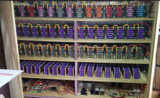
The benefits are that it makes pack spotwelding a breeze and gives you a good surface to solder substantial buss bars onto so your power draw on a, lets say 80p pack, can be reasonably even across the whole cell matrix. (All my (4) 14s80p batteries are pos and neg cell level fuse sheeted.) It offers an approximately 5 to 8 amp rated cell level "fuse" that will interrupt current reaching a cell that has potentially shorted. The idea is if a cell for some reason dead shorts in an instant the surrounding cells will dump their current into the cell causing a high current situation and the "fuse" will blow before any serious catastrophe can happen. Now to be honest there has to be a lot that happens prior to that scenario most of which will be detected way before such a catastrophic event occurs. Now mind you I am not saying it is not impossible but highly unlikely. There will definably be some unusual characteristics coming from this pack and it will certainly affect the whole battery.
One of those telltale signs as @OffGridInTheCity mentioned is a pack that just wont charge properly and stay balanced, forcing you to vent the excess from the other packs.
The scenario you mentioned about 400+ Amps to blow all the cell level fuses is not really realistic as most of us are only drawing maybe 250mA per cell which ends up being 20A for the whole battery. Even if you pull 500mA per cell you are talking 40 Amps. Now if you decide to short your battery with a homemade fuse......:oops:⚡⚡⚡
1642528296402.png
Then yea if the pos and neg weld themselves together than you will be thankful.
There is only one problem (the drawback) with this! The cells need to be pretty well charged for all the "fuses" to blow. After all you need at least ≈ 8 amps per cell. As your pack becomes smaller 40p or 20p the amperage that each cell needs to have available increases. Obviously the larger the pack the better off you are. I can see a scenario where you have a 10p pack and run a dead short across the pos and neg and get nothing but a nice glow from the fuses as the battery doesn't have the umph to blow the fuses. Although as each individual cell fuse blows it will cause the others to cascade as more and more amperage will flow through each fuse till they are all broken. This is an extreme example and hopefully we will never experience in real life.

The wrench you see above had literally a millisecond contact between the neg and pos of a 185Ah 14s80p battery. Quite a flash and a good wakeup call.
So as far as I am concerned the benefits of the cell level fuse sheets outweigh any minor drawbacks and it makes for a quite tidy looking build.
Wolf
1642530507410.png1642530574823.png1642530781975.png
 
Last edited:
The comments are good. But unfortunately didn't really address my question (in a way).

If a 4amp fast blow fuse can theoretically allow 3-4 amps continuous in/out of a cell. That could be very bad, but NOT blow the fuse. So the question is, what is the recommended fuse rate per cell?

I also know the "theorectical" 400amp is crazy high. but just an example. I have no intention of my packs ever going NEAR that much. I like the idea of 500ma per cell in my 80 cell packs. But I am about to start putting together a bunch of packs and trying to make sure I do it safely. So if a 4amp fast blow is technically still "bad" for a fast self discharge cell. What amp rating fuse should be used per cell?

It sounds like the nickel strip fuse only helps if a battery goes from fine to dead short. Makes sense, but we all know it's not always like that. So what is the recommendation at the per cell level? 1amp? 2?
 
I think this post https://secondlifestorage.com/index...-ofhc-copper-wire-as-a-fuse.11469/#post-80531
answers what i was looking for. Looks like even using something like a 4amp may be too high for safety. :)

Well... as much as I had hoped the nickel strip roll would work, just doesn't seem like it's a feasible option for second life packs. Oh well :) Maybe something will come along with a much smaller connector wire that's down closer. Spot welding tiny fuse wire is fun too 😆
 
The comments are good. But unfortunately didn't really address my question (in a way).

If a 4amp fast blow fuse can theoretically allow 3-4 amps continuous in/out of a cell. That could be very bad, but NOT blow the fuse. So the question is, what is the recommended fuse rate per cell?
It seems your thinking 'I want to protect the current flowing in/out of each individual cell'... but fuse wire is not ment for this purpose. It's true that cells have 'gas pressure' cut-offs built into the top to protect each cell but that's a different concept than cell level fusing as you parallel it into a pack.

Cell fusing is to protect the pack from a cell - not the individual cell from the pack.

To protect individual cells from excessive current the focus should shift to the design of the battery to work in a specific context.
Part of the 'battery context' is to protect the overall battery (and thus the max current to each cell) with proper breakers or fuses and BMSs and equipment that won't put the battery at risk even without the proper breakers or fuses.

I also know the "theorectical" 400amp is crazy high. but just an example. I have no intention of my packs ever going NEAR that much. I like the idea of 500ma per cell in my 80 cell packs. But I am about to start putting together a bunch of packs and trying to make sure I do it safely. So if a 4amp fast blow is technically still "bad" for a fast self discharge cell. What amp rating fuse should be used per cell?
When you have 80p cells in parallel, an individual cell is not going to get 4a vs the others only getting 1a, it would 4a x 80p = 320a for the whole pack / battery. All the cells in the pack share the amps (as long as the cells are reasonably close). The protection is provided by a circuit breaker / fuse on the battery.

If you have a single cell that starts self-discharging but has not yet degraded to a dead short will manifest in the overall pack becoming unbalanced - and the BMS is there to protect against this. If the individual cell is so bad it shorts out - THEN the fuse wire will protect the pack.

It sounds like the nickel strip fuse only helps if a battery goes from fine to dead short. Makes sense, but we all know it's not always like that. So what is the recommendation at the per cell level? 1amp? 2?
The recommendation is for the cell level fuse to allow 'at least' what you design the battery to deliver on discharge and accept on charge. And it can be higher than the minimum as long as the pack will burn it thru. On an 80p pack - it can be hefty which is why I don't worry about 7a fuse wire on 100p packs.
 
Last edited:
Not sure the circumstances where excessive current/cell would occur. Part of building a battery is to ensure it's sized for it's charge/discharge context and protected by circuit breakers or fuses. If you don't want 3a / cell, then don't allow it in terms of overall battery context.

It seems your thinking 'I want to protect each individual cell'... but fuse wire is not for this purpose. It's true that cells have 'gas pressure' cut-offs built into the top to protect each cell but that's a different concept than cell level fusing as you parallel it into a pack.

Cell fusing is to protect the pack from a cell - not the individual cell. And it's not needed to protect a cell from excessive charge/discharge via fuses / fuse-wire.

To protect individual cells the focus is on the design of the battery work in a specific context and protect the overall battery (charge/discharge) with breakers or fuses and proper equipment that won't put the battery at risk even without the breakers or fuses.


When you have 80p cells in parallel, an individual cell is not going to get 4a vs the others only getting 1a, it would 4a x 80p = 320a for the whole pack / battery. All the cells in the pack share the amps (as long as the cells are reasonable close). The protection is provided by a circuit breaker / fuse on the battery - not individual cells.


The recommendation is for the cell level fuse to allow 'at least' what you design the battery to deliver on discharge and accept on charge. And it can be higher than the minimum as long as the pack will burn it thru. On an 80p pack - it can be hefty which is why I don't worry about 7a fuse wire on 100p packs.
This definitely makes sense. I guess the concern is (based on what I saw from lots of other comments here and on various YT videos testing the nickel strip) was that if there is a steady current that is under the rating of the fuse that it could light it up. I had been planning for my packs to never really go above 30-40. I would prefer to have more packs if I need higher current. My current charge controller FULLY charging at peak can only do 80amps and it would be spreading that out.

I did see 1 or 2 comments (not many) mentioning that if you are making a small 10-16 cell pack that those fuse wires might not be good for that. But like you mention above, 80amps in or out of an 80p pack is going to be around 1amp each and that's saying that my pack level fuse is even that high. So realistically if my per-cell fuse pops around that 7-8amp mark that would happen if a deadshort and the rest of the cells tried to pass full current to that 1 cell. But otherwise having it at normal conditions i would expect to be under 1 amp per.

That being said, based on the size of your setup :) how do you feel about the nickel strip. Do you think in 80-100p packs that per cell "fuse" rating is acceptable?
 
That being said, based on the size of your setup :) how do you feel about the nickel strip. Do you think in 80-100p packs that per cell "fuse" rating is acceptable?
If I had spot-welded instead of doing the solder route - it would be OK. The nickel strips are above my 1a operating max and at 80-100p they will blow with 80a'ish for sure.
 
I guess the concern is (based on what I saw from lots of other comments here and on various YT videos testing the nickel strip) was that if there is a steady current that is under the rating of the fuse that it could light it up.
This definitely could be an issue. This is why temperature sensors are recommended to catch these kinds of slow heaters. But also, while using the BMS system, you should notice a pack constantly lagging behind the others during charging. This would bring in to question that pack to take a closer look.
Remember, BMS units are not a "set it and forget it and wait for an alarm" kind of thing. It still takes human monitoring to make sure things are still within expected standards.
 
This definitely makes sense. I guess the concern is (based on what I saw from lots of other comments here and on various YT videos testing the nickel strip) was that if there is a steady current that is under the rating of the fuse that it could light it up
This definitely could be an issue. This is why temperature sensors are recommended to catch these kinds of slow heaters. But also, while using the BMS system, you should notice a pack constantly lagging behind the others during charging. This would bring in to question that pack to take a closer look.
Remember, BMS units are not a "set it and forget it and wait for an alarm" kind of thing. It still takes human monitoring to make sure things are still within expected standards.
As I said before ^^^ above^^^ the 10p pack scenario.
Is it a possibility for someone to build a 4s4p battery using the cell level fuse sheets of lets say INR18650 25-R cells with a 20A max discharge rating and decide to pull 20A+ out of the battery? Sure thats 5A per cell and I am sure the fuses will get quite toasty. But that's not what the cell level fuse sheet was designed for, at least in my book. The idea was to offer a reasonable solution for pack protection while reducing the resistance of fusing to a minimum. All a fuse is is a bottleneck for electrons.

Considering the care and effort I put into building a battery I am quite comfortable with the cell level fuse sheets.
Wolf
 
I don't have much to add except that I agree with what has been shared already and personally am perfectly comfortable using the batteryhookup fused sheets for my 100p batteries. I also agree that is some situations, mostly small p packs, a smaller fuse would be better suited so insure the other cells can provide enough inrush of current to the failed cell to break the fuse. One thing that has not been brought up that is something to think about but less important than safety is that fuses do add to the total resistance of the pack and it gets worse as the fuses get smaller. Since the fuse needs to be hot enough to melt at say 1A that means it's resistance is likely going to be high enough to be producing some heat(aka energy loss) at 500mA compared to a higher rated fuse. In my system I use breakers on each series of battery packs sized to keep the max draw on any individual cell WAY below a danger point, 0.5-1A. I also use mechanical, a wooden and cement board box, methods to reduce risk of shorts within specific cell packs during operation and my own careful attention to metal objects while maintaining(sparks have happened but I quickly break the connection before anything heats up :)
 
Back
Top