

You are using an out of date browser. It may not display this or other websites correctly.
You should upgrade or use an alternative browser.
You should upgrade or use an alternative browser.
BMS advice needed for 7s8p or 7s16p solar storage
- Thread starter grossy34
- Start date

OffGridInTheCity
Moderator
- Joined
- Dec 15, 2018
- Messages
- 2,713
Eve 26v 18650 list as a 2550mah cell - https://www.18650batterystore.com/products/eve-26v-18650
16p * 2550mah = 40.8ah, which is light duty in terms of BMS balancing.
I would think any 7s BMS (with balance) that allows the load current you want would likely work - I don't see the need for worry or big $ in this case.")
16p * 2550mah = 40.8ah, which is light duty in terms of BMS balancing.
I would think any 7s BMS (with balance) that allows the load current you want would likely work - I don't see the need for worry or big $ in this case.
italianuser
Moderator
- Joined
- Feb 25, 2020
- Messages
- 781
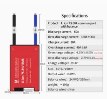
Possibly get yourself a BMS which can handle 1.5 / 2 times the nominal capacity of your battery. For a 40Ah battery a 60Ah BMS could be a good choice. You don't want the BMS to work at it's nominal limits all the time!

italianuser
Moderator
- Joined
- Feb 25, 2020
- Messages
- 781
Yes, that's it but you need the 60A version for a 40Ah battery.
The product's name is "7S 60A BMS", something like this:

The product's name is "7S 60A BMS", something like this:
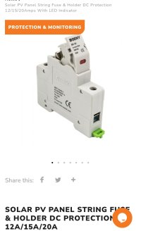
regarding my progress, battery still not finished as my portable spot welder was too weak to weld 0.15 nickel strip so i ordered a stronger welder and expecting it within a days, my inverter arrived and im stuck somehow with a breaker/fuse box for panels, asked seller regarding those and for my ac input 32a breaker is recommended, for a battery 120a one and for a pv panels 20a and my question is which one should i but for pv strings as there are few types but not sure if it doesn't matter which one will get or need specific one so advice needed, attached pics of them no.4 or no.5? also attached pics of my inverter details, ac input breker and battery breaker so please advice
Attachments
-
 Screenshot_20220614_234114.jpg246.7 KB · Views: 33
 -
 Screenshot_20220614_234233_com.android.chrome_edit_540477739608672.jpg159.8 KB · Views: 37
 -
 Screenshot_20220614_234316_com.android.chrome_edit_540516601575853.jpg238.3 KB · Views: 41
 -
 Screenshot_20220614_233554_com.android.chrome_edit_540084958366023.jpg209.6 KB · Views: 33
 -
 Screenshot_20220614_233508_com.android.chrome_edit_540102721769146.jpg172.6 KB · Views: 42
italianuser
Moderator
- Joined
- Feb 25, 2020
- Messages
- 781
To be able to control each string individually you can use a DC MCB (photo 3 "TOMZN MCB 125A DC" and photo 4 "DC Circuit Breakers All Sizes") with an amperage of 1.5x/2.0x your string amperage. If a string is for e.g. 10A then a 20A DC MCB will be ok (I bought 20A DC MCBs for my each of my three 8.64A strings). You choose a slightly over-dimensioned MCB to avoid it working at it's nominal limits. It's a good practice to disconnect panels from the inverter when doing maintenance.my question is which one should i but for pv strings as there are few types but not sure if it doesn't matter which one will get or need specific one so advice needed, attached pics of them no.4 or no.5? also attached pics of my inverter details, ac input breker and battery breaker so please advice
IMO It's a good idea to have an MCB for each string.
Some people just have a single MCB for all panels; if inverter supports two PV inputs then it would be two MCBs.
Photo n.5 is a fuse holder (looks like a model for 10x38 fuses, the numbers are millimeters), I use them in couples on both negative and positive. A good choice for the fuses is the ones with sand inside because they are more effective, when they blow, in extinguishing arcs which happen when interrupting an electrical line. I use fuses on the battery (between battery and inverter), with the amperage the closest as possible to the battery size. If your batteries are in parallel you could put a fuse holder on each individual battery; 10x38 are not the biggest fuses, for higher amps there's a bigger size (which requires it's correspondent holder, that means a 22x58 fuse holder and 22x58 fuses).
thx for info, bought them all, not arrived yet though, need some advice regarding daly bms
as is rated 60a but output wires are 10awg/30a?
is that ok or i should replace them with 6awg?
as is rated 60a but output wires are 10awg/30a?
is that ok or i should replace them with 6awg?
Attachments
italianuser
Moderator
- Joined
- Feb 25, 2020
- Messages
- 781
Oh wow, I was really struggling with this one! I found this other info which was about the relationship between Ampere and Power, which are not always proportional... but your answer is the correct one I thinkSince the wire has 200c rated silicone insulation it should do 60A uou can up size the wires connected to the b- p- wires
later floyd
---
(https://electronics.stackexchange.c...-awg-charts-rated-in-amperes-and-not-in-watts)
---
so i finally put battery and inverter together yesterday, solar panels were not connected yet as was out of time, wanted to check inverter so 26v charged battery (7s16p with a daly 60a bms) connected a fridge overnight but when i checked it in the morning inverter was turned off
and cannot turn it on as measured voltage from bms is only 7.95v but bypassed bms and battery shows 23.5v, is bms already done?, when balancing cables are disconnected voltage shows 16.95v, any advice what could go wrong appreciated
because of fridge?
and cannot turn it on as measured voltage from bms is only 7.95v but bypassed bms and battery shows 23.5v, is bms already done?, when balancing cables are disconnected voltage shows 16.95v, any advice what could go wrong appreciated
because of fridge?
What are the voltages of each series. If one is under 3V that it most likely caused over discharge protection 2.7V± .1V the cells bounce up after the load is removed. How balanced is the battery?
26V is 3.71v cell Just barely over nominal voltage, charge the battery up I would charge it to at least 28V before attaching any load to the battery. The BMS might start working once the battery is charged
later floyd
26V is 3.71v cell Just barely over nominal voltage, charge the battery up I would charge it to at least 28V before attaching any load to the battery. The BMS might start working once the battery is charged
later floyd

ajw22
Member
- Joined
- Nov 16, 2018
- Messages
- 733
Maybe that one started off with less charge. Did they all have the same voltage initially?why one series got 2.7v and rest 3.4v?
Or it has one or more "leaky" cells that's slowly self-discharging.
Or has less capacity than the others, thus was depleted faster. Perhaps one or more cells are not connected properly.
A basic BMS can only help with the first issue (the "balancing" function of the BMS), but it takes a long time to complete, and works only when fully charged.
The other potential issues require changes to the battery.
ajw22
Member
- Joined
- Nov 16, 2018
- Messages
- 733
Are you sure all the cells in the trouble module are properly connected? I don't know how your battery looks, but it's easy to miss a blown fuse or bad connection.all batteries were the same, brand new and had a nominal voltage
By "had nominal voltage", I assume they were all around 3.7V ~ 3.8V? If so, that part of the voltage curve can be extremely flat (see graph below), so some cells may have had as much as 70% charge, while others may only have had 40%.
Best practice is to either build the battery with fully charged cells, or fully charge each individual module after building, or fully charge the complete battery with a balancing charger.
The charger you bought in your last post is not a balancing charger, so your 3.4V modules may get overcharged past 4.2V while your 2.7V module plays catchup. The BMS will eventually balance the charge level over all modules, but it's going to take several hours, possibly days. Monitor the individual module voltage levels during charging carefully.

Silicon Lightworks
Battery powered LED trade show lighting for pop-up displays & retractable banner stands. Portable arm light fixtures for trade show booths, art fairs, craft festivals & other exhibitions....