BMW i3, SimpBMS, Victron Multiplus 48v 5000 build

Darkwing

Member
Joined
Feb 10, 2021
Messages
37
My attempt to build a powerwall.

I will try and give as much relevant information that i can here.
I originally wanted to go for the Commercial Tesla Powerwall, but it can not be obtained in my country (Denmark). So i went for plan B.

I have an existing solar installation (multiple actually) Theoretical capacatiy at around 15 kwh mark, actual seems to be about 13kwh, I have a Growatt battery already, but it is under powered and has too little capacity.
So time to build my own.

I like everybody else wanted Tesla batteries, but they are quite expensive these days running at around 1200eur each. In the hunt i fell over SimpBMS, that supported Leaf and BMW i3 batteries. Both reasonable available. Originally wanted the leaf because of capacity, but found that the BMW was easier to locate and have shipped (Damn you Corona). Normally i would have driven to any place within about 1.000km to get the battery, but i cant.
Found BMW i3 battery on ebay, 3500 eur + shipping of about 400 eur.
In one of the SimpBMS threads i noticed another Dane (Lykke), he gave me some advice and one was to contact egomotor in Lithuania. They offered a 60ah pack for 3000 eur and 200 eur shipping. On Lykkes recommendation i also got the power cable from battery towards car (Great advice) for another 50 eur (i think it was).
The adventure was on.

Lykke gave me much advice and even managed to arrange that i could see his actual install, this helped immensely. He warned that the big parts may seem expensive, but many of the other components will end up costing quite a bit of money. He ended up being very correct.

Main purchase list:
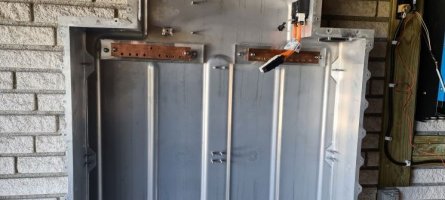
BMW i3 60ah battery, if you can go for the 90ah one, seems like better bang for the buck.
Victron Multiplus II 48/5000
Victron DC-DC 48-12v
SimpBMS
Victron Color GX (Thanks for selling me yours Lykke)
Victron Smart shunt 500a (may be to small i will learn soon)

Other than that there was things like:
Large diameter cable 35mm2 (from batterypack to inverter)
Minor diameter cable 25mm2 (internal in battery pack). Lykke said he used 16mm2, but my brain liked the 25mm2 better. No good reason....
8x Fuses (Lykke had 60a 58v fuses after each battery in the pack, so i followed), we both went for the MID, but it feels flimsy. May change this some day.
Busbar (Lykke said this was an expensive and a bit elusive part he was right. Ended up with copperbar that i milled myself, se more later).
Link connectors 35mm2 and 50mmw (bought 25mm2 but they didnt work well, se more later).
Connector rings 25mm2 and 35mm2 to connect individual batteries to busbar and to connect bmw control box to busbar. And for me also the smart shunt.
SERIOUS cable cutter (bought large single hand and a large dual hand)
SERIOUS cable clamper (dual hand se more later).
Combined DC fuse/breaker between batterypack and Victron multiplus. Expensive, again Lykke warned me.
Cable heatshrink 25mm2, 35mm2, 50mm2.
Protective cable shroud (approx 20mm2 i think)
Plexiglass (75cmx50cm, 5mm think) to build busbar "container", more later.

And then loads of bits and bobs, plus tools of a more generic term. I will do my best to illustrate, and remove as much as possible of my failures, so i dont confuse you too much. Ie. i severily over bought link connectors in 25mm2 that it is silly, and ran out of 35mm2.

I will try and add as much photos as i can without bombing the board completely.

One final note, my initial route was to look at the battery in its original configuration at 300v+ DC, and then have a Growatt inverter working against it.
Carel strongly recommended that i did NOT do so. Reason is that 300v dc is more serious than 300v ac. I personally still feel that it is the right way to go, but could not find enough documentation to prove it. I do believe that work is in progress enlighten the area.

Oh and i'm not an electrician, just a software geek that likes gizmoes.
Also i live in a country with strict regulations on electricity, so i will need to use an inverter that is on the "safe" list etc. Finally I will need to employ an electrician to verify and connect my setup to the Mains.
 
Another little challenge, is that i need the powerwall to be grid connected, and therefore need a smartmeter to control flow.
When i started the EM24 seemed the only one available, which sucked because i allready have the SM630 for the Growatt.

I found a thread working on adding the SM630 into the open source part of Victrons software. and before i knew it they had completed the change. I have added it to my Color GX, it is not super clear where their software parts go "upload to your device".... ehm the inverter, the color gx the smart shunt, the SM630. Luckily some of the screenshots lead me to going for ssh access to the color gx, and that seems to be the right way to do it. I haven'nt tested it yet but will as soon as i get a few issues with can fixed. The can pinout in the SimpBMS for the i3 is not great, and i didnt quite get photos in the right angles of Lykkes setup. Im currently trying to measure out if i connected it correctly.

I have sourced most of my parts on ebay.de, since they seem to be the ones that can help, after breexit has made ebay.co.uk close to worthless for smaller items.

I will add photos and steps over the next couple of days
 
Sounds like a well planned out system hard to go wrong with a EV battery. there a few here most have used either 48v or 60v dc. Hope to see photos soon.
later floyd
 
Your going to need to reconfigure the packs to 48v - you cannot use them with Victron gear at 300v ?
 
So time to add some more information. (I'm struggeling with time on work, actually building it, and documenting it at the same time :)

Box arrived from EgoMotor, it about the size of a queen size mattress. approx 120cm wide and 180cm high. All in a nice wooden box. Unfortunately it took nearly three weeks because DHL managed to misplace the battery, somewhere between sweden and denmark.
Super nicely packed, with a loot of screws.


BatteryWrapped2.jpg

The battery has a lid that is hled in place by a large number og hex bolts (think it was 25size.

You will see the 8 batteries inside, they are held in place by m6 nuts on bolts that are welded to the battery tray.
I recommend using a 10mm top, a long extender and a rachet to get them loose. They can be a bit fidgety to get out.
Each battery has a major battery cable going to next battery, easy to get of with your hand. It also has two small connectors pointing to the center of the battery tray:
BatteryboxOpened.jpg

The two smaller handles CAN and temperature + balancing wires. .They can be disconnected by hand.

CanbusConnector_Blue.jpgContactorConnectorWhite.jpg

The control cables are held in place with a rather annoying grommet:
CableMountedToBatteriesGrommet.jpg

I lifted out the batteries in a pattern going from top to bottom and put each set of 4 on a roller. (visible in the bottom of the picture.
batteryConnectors.jpg

The individual battery is quite heavy, so expect to wrestle it a bit to get it out.

At the bottom there is a slightly different power connector, just unscrew it we will look at it later. The aim is to pretty much clear the tray so we can mount as easily as possible.

Below the 8 batteries, there is a heating element:
EmptyBatteryTray.jpg

I will remove this since i dont need to worry about heating/cooling. I wont be able to draw enough current to affect the batteries.
 
Last edited:
Having removed all 8 batteries the tray is fairly manageable.

I removed the heating/cooling element, disconnected tube/connectors, and also a few electrical connectors (orange), they seem to control the heater. It includes a temp sensor that i deemed not relevant, so it went too.

OrangeTempConnectors2Marked.jpgOrangeTempConnectors1MArked.jpg
Having been quite inspired by Lykke, i decided that a wall mount was the way to go. I spend a long time debating with my self if i should mount the tray directly to the wall or have a wooden plate between. (My wall is quite uneven). I ended up mounting it directly to the brick wall. I bought some heavy duty wall mounts at Biltema (common in the nordic region) They were essentially expansion bolts. I decided that it would be ok if not all holes would hit a brick. Those would not be used. I was very focused on the top ones, they are my main bolts. I put some wood beneath to even it out and mounted the tray to the wall.
EmptyBatteryTrayToBeMounted.jpg

WallHoles_Side.jpgWallHoles_Top.jpg

Mounting can be done by a single person, but i recommend being two. I tend to do my things on my own (engine changes, gearbox changes etc).
The bolts i believe are m10x40mm, sot they are not going anywhere.
REMEMBER take care of mounting busbar BEFORE mounting it to the wall.
 
Last edited:
So next step was to build a busbar (power distributor plate). I would have prefered to buy one, but Lykke warned me that there were few products and they were quite expensive.
The need for the busbar arises, because we need to configure batteries in parallel rather than serial as it came from BMW.
We need to busbars, one for positive cables and one for negative cables.
One of the reason that it is hard to find commercial products is that i would need to be 9 pin or more. Most seems to stop at 6.
So i decided that i would build my own. Quite a bit of tinkering went on and i arrived at a copper bar, with plexiglass as insulating layer. Aluminium is not conductive, but i would prefer to have an additonal layer, and choose plexiglas, since it was available in (you guessed it) Biltema.
I bought the copperplate from a local metal shop (they have a parts bin, that tends to be cheap). I ended going a biiiit overboard. I bought 7 kg of copper :). In essence i ended up buying enough for 3-4 battery packs.
I overengineered and oversized it .. a lot. I made them 10mm thick, and 50mm wide, and approx 320mm long. In retrospect it could be somewhat thinner. maybe 5-6mm would do. Look at the busbars at the contactor in the battery and you will see why. They are more like 4mm wide. (picture will follow somewhere below.
BusBarBoltPattern.jpg
I drilled out two mounting holes(10mm) at the outer edges of the busbar, and then made eight holes(8mm threaded) of tp one of the sides. And finally one single 8mm threaded to the opposite side of the eight. Reason: one to go out of the battery and eight to go in. I used the cable connectors to determine how far in i could put them and how far i should space them out.
BusBar_BasicMount.jpg

Mounting is a 8x50mm bolt going through the back of the batterypack, through THREE layers of plexiglass.
BusBar_MountingSpacing.jpg

Idea is: initial layer is insulating, second layer holds mounting bolts for the actual busbar, third layer holds it all together and gives needed stability. The second plate has drilled out holes to acommodate the two bolts facing the busbar.
BusBar_Bolts.jpg

I then didnt have a nice spacer so i used an oversize bolt,. and then a 8mm bolt to provide a mounting surface to the busbar.
Of course you need two, one for positive and one for negative:

Busbar_BothMounted.jpg

The busbar is somewhat inspired from the one that Lykke purchased.
 

Attachments

  • Bubar_BothMounted.jpg
    Bubar_BothMounted.jpg
    56.2 KB · Views: 129
I had removed the entire heating element including the shroud going out of the battery. I decided that it would be more "correct" to add it back in, so the heater element had to be split. There are two lines going into a connector that can be split from the housing, result:
CoolerConnector.jpg

CoolerHousing.jpg

The keen eye will spot that one of the bolt holes looks different.... broken bolt, i drilled it out afterwards and remounted the shroud to the battery tray.
CoolerHousingMounted.jpg
 
IMG_20210525_171910_280R.jpgIMG_20210525_171620_852r.jpgIMG_20210525_181020_520r.jpg

OK,
can wire connecto tor SIMPbms J5 connector = 10 pole Molex minifit series
from BMW battery take the can cable that connects the modules bms slaves, CSC's, cut cable at the blue connector
disregard the blue cable.
2x white red = pos out 5V on pin 5
2x white brown = gnd on pin 10
2x yellow brown = CAN H on pin 4
2x yellow red = CAN L on pin 9
1621960356751.png
If your SIMPboard has a can termination resistor use it, else crimp a 120 Ohm between CANL and CANH
use a blue termination plug in second canbus port if using Victron GX device,
Both ends of the can bus need to be terminated with a 120 Ohm resistor.

Please make sure to check if GND or POS have been connected correct,
a wrong connection will blow up all your bms-slave boards....
and absolutely do not think these will run on 12Vdc
 

Attachments

  • Simp BMS Setup Manual V0.25.pdf
    1.5 MB · Views: 1,607
So time for an update. Can see i forgot a few things about the disassembly. the right tools helps. I use an electric impact gun(wheel lug nut thingy), combined with a 10mm top.disassembleTools.jpg

That makes it a dream to pull of all the bolts. The (outerskin) bolts also offer the option of af hex t30. But since we need a 10mm top to get the batteries out... For this we also need the extender, since the batterys are about 15-20cm heigh. Remark the converter from normal "umbraco" to ½inch top. They are brilliant to adapt the tooling.

Next step Rewiring the battery. This very easy but also tricky.
In theory we cut the connectors, splice a fuse and extended wire into them and connect them to the busbar.

However as always, the devil is in the detail. Again i was super lucky that Lykke offered me to watch his setup, and thereby learn from him. So basic things like where to cut the cable to ease cable management, cable draw ideas etc helped alot. Funny enough... i still did it my way :) (Sorry couldnt help myself.)
Lykkes design on the cabling is better than mine, it sits prettier and flows nicer. So you may want to think this part over.
Lykke also mentioned a detail i wouldnt have though about, cable length. It seems it is recommended that all cables have equal length to ensure same resistance in cables. Since Lykke disregarded it on his second battery, i decided to go the same way. Cabling would just be to messy. And at least in theory it should get balanced while running anyways.

So as not to forget tooling:
BatteryCable_ToolsPicture.jpg

This is what i used, wisegrip, an 8mm wrench?, a sharp knife, a serious cable cutter, a automotive solder machine., normal cable cutter, voltmeter, the mounting clap device thingy, and a metal tube cutter. You may also want to get a metal hack saw, depending on if you will remove anoying edge on a single battery. (top left).

Materials:

Lykke used 16mm2 but i fell in love with 25mm2. (i'm not a certified electrician).

Red 25mm2 cable about 15-20m depending
Black 25mm2 cable about 15-20m depending
9x Midi fuse+box (decided to go for 58v 60 amp, may that should actually be smaller). The midi fuses are tiny physically, more later. Got a spare..
16x cable connector clamps 30mm2 (buy 20 so you have something to screw up). And yes 30mm2. Cables from batteries are larger than ours.

Pr battery:
For the red cable(pos) we need 2x25mm2 / 8mm hole connectors and one 25mm2x10mm connector. Maybe 3 x 8mm would do. I overengineered it i think.
For the black cable(neg) we need 1x25mm2 / 10mmhole or...
So for ease, we need 4 pr battery or a total of 24pcs of 25mm2 / 8mm hole. Buy 30 or more. You will screw up some of them.

We need a shit load of heat shrink material. It needs to fit at least the 25mm2. And a bunch of electrical tape. If you can i would get them in red+black.
Also i would recommend that you get some electrical tubing just big enough for the cable to fit. Cables will be "cutting corners".

So that sort of sets the shopping list. I went completely overboard and bought 50m cable... that was overkill. The battery part of the battery box is about 130cm heigh and about 80 in total (dont forget 4x2). Each battery is about 15cm deep x30 heigh x 35cm wide. So worst case i would say about 2m-2,5m cable length for each of the 8 batteries, but if you run "logical" lengths some will be considerably shorter.
The cable connectors cobber tube to connect two cables are a bit of a mess. They need to fit the 30mm2 from the battery side and our 25mm2. I put the battery cable directly in, and folded the connecting battery, to ensure sound connection.
 
Actual mounting:
When in series, there is a short cable jumping between each battery, and an odd extender at the bottom of the battery. It allows BMW to use the same batteries anywhere by just adding the extender.
We need to cut this cable, i measured it out so the cable connector would sit at the cable holder:
BatteryCableWhereToCut.jpg

You can sort of use the barcode sticker as a navigation tool:
BatteryCable_Connector_Cut.jpgBatteryCable_PlugCutClose.jpg
Just leave a few mm after the sticker and it should be fine (he said not having closed his battery pack yet). This is the negative lead (measure to make sure, trust no one).
The negative cable is to run to the busbar without fuse, i only fused positive cables. Measure out, dont forget corners take up distance, and that some will need to cross the battery box to reach busbar.

The connector clamp i learned can be set to connector size (i actually broke the first one, because i thougt is was one size fits all.... it is not).
BatteryCable_ConnecterClampAdjustment.jpg
Push it up and select the size needed. Then you wont break the tips like i did.
Remember to put on the heatshrink material. I put it on the battery connector, then clamped the cable connector on to the cable ends. The extending cable will need to be folded otherwise the material thickness will be problematic. BMW uses some aluminium type material and i use copper, i believe that explains the different thickness's.
Use the soldergun to heatshrink .. the heatshrink material in place.
For god measure i use electrical tape too, old habbit i guess. I also put it on the final end of the cable to ensure no sparks (both pos and neg):
BatteryCable_safety1.jpg

I then added electrical tubing to protect the cable especially from the corners of each battery :

BatteryCable_CableTubing1.jpgBatteryCable_CableTubing2.jpg

I dont like the sharp edges. The battery is fixed to the wall, but still.
Speaking of sharp corners on the picture with my finger you can just see the edge that on the top left battery is a bit "un-cool". You may want to get rid of it when it is NOT in the box.

On the other end we put a connector to be connected to the busbar:
BatteryCable_posConnector.jpg
Sorry for red cable, no pictures of black cable avail.

The positive is a bit more work. The cable is fused to the battery, and we use a cable connector and heatshrink to connect it to a fairly short length of red cable.
BatteryCable_PosCableInit.jpg
Maybe about 40m of length.

BatteryCable_posCableSecond.jpg
I used a bottle of antifreeze to support the cable. If you are a one man band like me, this will end up being a problem. Keeping cable in position and clamping it with both hands.

This new length of cable goes to the midi fuse box:

BatteryCable_fusebox_visible_side.jpg
The Midi fuse is quite flimsy. I dont understand how come i need high end cable and then a small ass wusy fuse out of approx 1mm think connection points.
You can see that i choose to add washers on the outside, this is because i bought too many 10mm connectors, think it may still be "icky" with 8mm. So buy a bunch of washers.(at least 5mm hole)

Again i like electrical tape:
batterycable_fusebox_complete.jpg

I want a fuse as close to the connector as i can get it, without problems with closing or twisting the cable. I decided that the fuse should be just after the cable has bend around the battery it is connected to:

BatteryCable_FuseBox_Mounted_Nicefit.jpg

And of course a bolt/cable connector at the end, heatshring and electrical tape.

Lykke warned me about one thing.... your arms are going to hurt.... he was right. there are many many heavy compressions and cuts to make.... tender muscles = found.
 
Ok, so i mounted all but the two top batteries, and created all the cables as described. Reason: better access to the busbars.

Lykke and i mounted it around the same way, he used nice commercial grade items, i went diy. This may be the reason why he's cables mounted nicer than mine.
Getting the right mounting flow (what batteries at what time ... i cant say, struggled a bit with this part, so had to re pull the wires a few times. Still think it was smart not doing the two top ones incl mounting until last.
Problem is that you will have positive on one side of the batterypack and negative on the other. That means we need to pull some quite lengthy cables to some of the batteries. This is of course especially bad for the two bottom ones, furthest away from the relevant busbar. I pulled the two bottom once's along the bottom of the pack. Lykke pulled all over the top of the pack.

Before mounting the cables, disconnect negative plug from batteries for safety.

Mounting is quite basic, draw cables as protected as possible, bottom onces should be closes to bottom of batterypack.
Busbar_negative_Few.jpgBusBar_positive_FEw.jpg

Also we will need (i did) to remove a small plastic bracket on most of the batteries:
BatteryCable_RemoveBracket.jpg

You should end up with 8 batteri's with each their connection to the negative bus bar and positive busbar.

I have negative on right and positive on left. Think that Lykke has it reversed of me. For me the cables from the top box could then be used. (More later).

We now have the batteries mounted in the tray and connected to the busbars.
 
We are now getting to the point where i start to struggle, the visible evidence from Lykkes install and the online documentation, is not super clear from here on in.
Things from here on down are subject to change for now:

Initially we need to sort out the remaining internals of the battery. We need to use the original contactor/fuse box.(top of the batterypack) We remove the BMW battery ecu, it bolts of easily.
ControlBox_Ecu.jpg

There are a few torx bolts, think it was t25. Also there are three connectors, they have en simple slide mechanism to extract the cable, if you are using force to get them out... you are doing it wrong.

There is a basic plastic lid on top of the box behind, that can be opened by fingers or a screwdriver.

After the lid is off this will greet you:

ControlBoxOpened.jpg

A quick description, be aware that this may be inverted, since cables coming out of box can be "twisted" at Victron.
Negative contactor:

ControlBoxOpened_NegativeContactor.jpg

Positive contactor:

ControlBoxOpened_PositiveContactor.jpg

Fuse:
ControlBoxOpened_Fuse.jpg

These three components are controlled by SimpBMS to ensure safe operations. This means that if overvolt/overtemp is detected it will stop power to contactors, and they will close the connections on both cables.
Lykke has operated out the computer components beneath since they are not needed. I haven't ... yet...

I have disconnected most of the auxillary power (control of heat/cool element etc cal).
 

Attachments

  • CoolerHousing.jpg
    CoolerHousing.jpg
    73.9 KB · Views: 116
Since we are nearing the point where i am at, i will skip a bit, as not to post uncertain data.

We need to connect the databus back to the batteries, and prepare them to be connected to SimpBMS. Lykke has choosen a very clever way, he has desolded the connectors from the battery ecu, soldered them to prototype boards (one for CAN bus, and one for Contactors/precharge). It is the white plug and the blue plug.
I personally cant get my self to butcher the ecu (yet), and also dont like the thought of cutting of the other end of the connector and soldering it all together directly. Currenctly im on a stick in prototype board, since i have/had some issues getting it all to work.
 
So it is Vitron time now. There are two components, again inspired by Lykkes setup:

Victron Multiplus II 48/5000, most others use the quad. but it is not whitelisted in Denmark, and i cant use it. Multplus is whitelisted, but maxes out at 5000w.

We also have a dc-dc converter from Victron, the Orion-Tr DC-DC 48->12 110w https://www.victron.dk/shop/24-orion-tr-dcdc-convertere-isolerede/891-orion-tr-4812-9a-110w/
This provides us power to run several components, the Victron Color GX (Thanks to Lykke for selling his surplus to me). It will also power SimpBMS, and maybe a relay (To be determined).

So as mentioned we have a Victron ColorGX (could be any GX device as i understand it).

Then i have the Victron SmartShunt, i choose the small one, it is rated at 500amp...
I'm currently not 100% sure that this component is actually needed, or if i can rely on either the Multiplus or SimpBMS/Can.
Important note, the Smartshunt needs the same current level as power supply as it measures, otherwise it will show power supply voltage. I tried with 12v because the manual for smartshunt didnt lead me to think of it as anything but power supply. But it seems to link in to the power in the measuring cables.

Finally i have a large DC breaker/fuse as again... recommended by Lykke. It is expensive, hope that other solution can be source. I ordered some chinese DC breakers but kind of lost trust in the. The breakerbox is expensive in my world, and it is hard to get fuses at the level we are looking. And it was only avail in UK = import fees to get it into EU... yay....

I also ordered the BMW powercable with my battery, to ease connection to the battery box:
BMW_PowerCable.jpgBMW_PowerCablePlug.jpg

The plugs make it very easy to plug and unplug it. Not really relevant with the breaker...but hey.
Will update with pictures, dont have them on computer currently. More to follow.
 
Ok, i have the system up and running.... ish. There is some configuration i cant get my head around. More about that later.

IMPORTANT READ THESE LINES BELOW

I have found that using the connectors from the busbar towards the fuse/contactor box (using the BMW ones), is a BAD IDEA.
They will clearly overheat, and i know why. They are aluminium, not copper. It is not a problem from each battery to the busbar, but coming from the bus bar and onwards, you will have the collected amps of all 8 batteries. Running it at about 2kwh load (spa pump/heater), i learned that this cable becomes unacceptable hot.
Solution is to replace cable with cobber one, but that will loose you the very nice clicky feelt the original gave you. Sucks, it will also expose the conenctor somewhat. (more about process later).
I have initially used 35mm2 cable, but i dont think it will withstand 5kwh sustained power, even if it is just for about one meter. I will upgrade mine to 50mm2, but it is not easy to source locally.


IMPORTANT READ THESE LINES ABOVE

Ok so how to solve, since one end is bolted to the busbar, that end speaks for it self. The other end, however we loose the connector. I drilled the connecting busbar coming out of the fuse/contactor bar. But i made an initial drill big enough for the bolt, then made a way bigger one to allow the connector to fit and come in from the side. Bolted it together, and put electrical tape around the plastik coming from the box.
The busbar from the fuse box, seems to be made of HARD copper, i went through many drills to find one that even dinged the damn thing.

Other notes: it seems that the cable going from the fuse box to the outer batterypack connector is made of copper. It gets warm running at around 2-3kwh, but not hot.
I'm still debating with my self i i need to ditch all the BMW wiring from the busbar out. If i do it will all be 50mm2.
If you are running the 3kwh inverter/charger, i think the 35mm will do. But i have the 5kwh one (5000va to be exact). Specifications indicate that 35mm2 should do, but it gets warm to the touch running at the 2-3 kwh mark. I would guess around 40 deg centrigrade. US guys... ask google :)

The BMW cables from the fusebox and out are copper based, so they are not quite as sensitive as the aluminium ones. Currently im wondering if i should limit it to maybe 4lwh or about the 80 amp mark, rather than the 100amp mark i have it on now.
 
Ok now for the more interesting part, and unfortunately also the more messy part.
Getting it all to work. There is quite a few lessons in here, most of them Lykke helped me crack, but since he is not grid wired, some things i will need to do on my own.

Components in current setup:

BMW i3 60ah battery
Victron Multiplus II 48/5000
Victron DC-DC 48-12v
SimpBMS
Victron Color GX
Victron Smart shunt 500a (may be to small i will learn soon)
EM24 ETHERNET based smartgrid meter. Be aware versions with usb/serial rs485 are around.
I really wanted to use my current Eastron SMD630, and others has made a plug in for it. But i think i lack the understanding of how the serial rs485 signal is to enter the Victron Color GX.

So first simple item we need 12v dc power to run our auxiliaries. I run a fused cable from the fuse/contactor box, and run it to the Victron 48/12 converter. It is the smallest one they have, we don't need a lot of 12v power, we will run the SimpBMS and Color GX from it. The Color GX takes i think 12-70v, so it could be run directly from the battery. I put a 12v 5 amp fuse as near to the battery connector as possible. You can reuse the connectors used by the old BMW board components (in the fuse/contactor box).
From the converter i again put a fuse 12v 5 amp on the outgoing posiitve cable going to the Color GX and Simp BMS.
For practical reasons i split the power in the box that holds the Color GX, and distribute it to both Color GX and SimpBMS.
Initally i thought that the Smart Shunt needed 12volt too. That was WRONG, it needs the same 48v positive to is positive connector (small thing on the small electronic box. I also run 48v negative to the negative measure point of the smartshunt.

Smart shunt, do you need it..... well im still not 100% sure, i use it for one thing, to see the actual power flow, but the only really usefull thing it gives is volt/amp flow. It shows an pct, that tends to stay at 100% unless i really stress the system. Dont get that logic. Maybe i just dont understand what the pct represents. The Smartshunt needs a ve.direct cable... it doesnt come included ... no idea why. it is a basic 4 wire connector so you can get creative here.

Of course the negative power carrying cable from the outer pug on the batterypack goes to the Smart Shunt measure point. The smart shunt very clearly indicates what goes towards battery and what goes towards inverter. From there it goes to a combined fuse/mechanical contactor that pulls both positive and negative. The negative from the Smart Shunt goes here, and the positive from the outer battery pack goes here. This is the primary power cables im talking about.
If you keep the components close (You will prefer to do this trust me, DC doesnt like distances), then the BMW cable will get you very close to all the way to the inverter. You may need 1 meter of 50mm2 (35mm2 for 3kwh).
The cables from here goes to the Victron Multiplus positive and negative connectors.
OF course make sure all is disconnected when doing this.

The Victron Inverter, needs as a minimum:
Positive an negative Primary power from Batterypack
220/240v volt to AC1 IN
Earthed wire
VE.bus (i think it is ) as RJ45. use regular ethernet cable here will be fine.
Ethernet to reach the EM24
For configuration the Victron Mk3-usb -> VE.Bus converter. Essentially a rs485 to usb converter, but it has some quirk in it that makes normal converters not work (for me anyways), Cost me approx 100 usd.

The Vicron Multiplus sports two AC out, the first is defined as also in. This is meant for AC solar power inverter. That will allow full islanding if grid fails.
When you read the Victron documentation, it will state that you can run without a smart meter, that can be done by using the AC out1 (i THINK!!).
Another little quirky thing is that you can connect DC solar power directly to the primary DC power connectors. I think this means that the solar needs to operate in the 48volt range, and i personally wouldnt do it. To scared that it could peak onto the lithium battery = not good.
Configuring the Victron equipment is not super logic either. since there is software to configure the Color GX and software to configure the Multiplus.
To configure the multiplus via the Mk3-usb interface you need VE.Configure, that is actually more named VE configuration Tools. DONT let their webpage cheat you, the VE.Connect is for things like the Color GX etc.
The VE.Configure, allows you to configure the inverter/charger. This means setting volts, ampers, select country grid, setting up an assistant (that is essentially just a sub configuration of the multiplus. I initially thought that the Color GX controlled it all, but no, it is shared somehow.
I will come back to the actual settings, they are currently a work in progress. I can tell you that 4.2v(x12) is definately max and Lykke stated that BMW charges to 4.15v and maybe we should settle for 4.1v. Bottom is a bit more unclear, it seemt it can be set very low, but i have currently decided that 3.1(x12) is my floor.
The multiplus handles a few things like throthling back charging when closing to full. It also offers an excersice battery plan, which i personally like, since i will have 3 months of near no power at all coming to the bank.
Many other trigger points can be set as well, ie after a "full" discharge, how far backup should the volt come before it allows discharge again etc. Pretty nice, but all these features is also where i struggle, because there are so many options, and what decides over what. I will try and tweak my setup as best as i can and inform you. The most important is that you dont overcharge the battery, I have set a max charge current of 48.5volts. To ensure it doesnt overcharge.

Victron Color GX, has a loot of plugs_
Basic VE.direct connectors to be used towards the Smart Shunt.
RJ45 VE.bus connector to the Multiplus
RJ45 VE.Can connector to SimpBMS
RJ45 VE.Can Terminator (buy the damn thing (it is a 120ohm resistance inside i think), i got mine with the Color GX from Lykke).
Ethernet
Usb (for Wifi /GPS (why gps??)
In theory it should be able to take a RS485 to usb connector, but only their own i think (my chinese failed), and i cant find theirs for purchase anywhere).
And of course the DC power 8-70 volt, so either from the inverter or directly from the battery. Remember fuse regardless.
 
We also need to connect SimpBMS, this is both fairly easy and very difficult.

The SimpBMS is trying to do alot at once, and the documentation shows it. It is hard to tell running and EV and ESS from each other.
It has a series of plugs, some are used some are not.
Carel offers multiple versions (with screen, with connectors etc). Personally i find the SimBMS to be somewhat overpriced, but the auxiliaries are quite fair in price. i think my SimBMS price was around 375 euro. Im paying this because Carel has helped and adviced me and that has value too.
A fair pricepoint would be around the 150 euro mark. But beggars cant be choosers. The extra parts are nicely priced, i bought it all :)
The software is quite good but has a few quirks, that caught me out. No showstoppers, but learning points. More on this later.

The basic stuff, what needs to be connected to SimpBMS:

RJ45 VE.Can from Color GX
Power 12v from 48-12v converter. Would be cool if it could live of the same volt range as Color GX (8-70).
I recommend a permanent usb cable that is accessable from outside a housing.
BMW i3 can
BMW i3 Connectors (positive and negative) and precharge.

The BMW i3 CAN was an absolute nightmare to understand the wiring. The wiring on the SimpBMS Manual... sorry guys... sucks.
If you like me dont know alot about CAN, this is confusing. CAN network is to be seen as the good old BNC network.
This means it NEEDS terminators in both ends. It also means that everyone(clients) has a dropline from the mainline.

I will make a nice drawing soon, but time is short these days.

Terminator -> BMW i3 CAN plug in/out (one side) -> Batteries -> BMW i3 CAN plug in/out (other side) -> drop to SimpBMS -> terminator.

Terminator is a 120ohm resistance. if you only can find 100 and 20 set them in series.

Lykke has made a super nice solution where he desoldered the plugs from the BMW battery ECU, soldered them and the resistors to a prototypeboard, and fixed them with hot glue (i think it was).
In currently using plugin prototype boards, it is ugly and unstable, so i will need to at minimum go from plugin to soldered, most likely i will desolder the connectors from the ecu and use them on the board too. Alternative is to remove the connector from the harness from the batteries. But i really really hate cutting cables up, especially expensive hard to get items. It seems most others chop the connector off and just solder the wires together. also an option i guess.
Will decide what to do soon, so i can close battery pack backup.

What really got me was that i had to use both 4 signal wires in all to make it work. I tried for the longest time to get it to work with two. no dice at all. Also it is the blue plug coming from the Fuse/Contactor box.
I will post the exact wiring as soon as possible. Again Lykke was a great help, and on his second dig through his notes, he found the gold i needed to understand the exact wiring.
The documentation is very unclear on whether the documentation relates to individual batteries or the end of the CAN cable. I suspect that itt targets individual battery, much like the first note Lykke found. The plugs seem the same, and has same amount of pins, but they are apparently different.
Second part is the contactor and precharge (work in progress), again Lykke came through, as i understand it SimpBMS relays 12v power out on three sets of two plugs on one of its connectors. These should be wired directly to the connector coming out of the Fuse/Contactor pack (black).
Im still not 100% sure if i want a classic relay in there or not. Right now i have actually hotwired it via the DC converter. DO NOT DO THIS, it circumvents SimpBMS cut off capabilities.
It seems that the intial settings of SimpBMS may not be right to keep the contactors and especilly the precharge in order. I will do initial try on cabling directly. I tried it initially but a lot of problems blocked me. Lykke has one with relay and one directly from SimpBMS.
Be aware that actual current is being pulled over these cables, so distance matters. I think this was one of my major mistakes, trying to use cat 5e RC45 cable to pull the currents. Will most like try again but with 6e instead.
A few annoying details about the SimpBMS connectors, they are a bit sensitive, and i had to try many many many....... many times to figure shit out.
Currently i use classic single plugs, and they connect beautifully, where the clamp style ones inside the connectors from Carel are sensitive to many clip on/offs. It may just be my crappy skills. Maybe the connectors should be prewired, that would solve the issue.I would happily pay extra for it.
Final detail i havent solved quite yet. The extra screen for SimpBMS, (which comes with some random firmware on them btw), needs to use wires from the same connector as the battery, and they both need the 5volt power in the same plug. (5volt for the CAN network).
Im not sure how i will solve this. It is not hard, but what is "best practice". On an important sidenote, SimpBMS actually has a second 5v power outlet in another plug, so mayb the can cable should just be split over two connectors, so screen can be just one. Or reverse.
Screen needs other firmware, can be found via link on SimpBMS Github page. You will need an SD card (small like 1-4gb) to flash the screen.
This part worked exactly as described.
Carel has be willing to answer questions directly to SimpBMS, but not really when it came to the integration towards the Victron equipment.
I thought they had a running system, that they could essentially just give me a copy of configurations/settings etc, but this has not been the case.
Please be aware that Carel has been very helpfull otherwise, he has just choosen how far hi's support goes, and that is fine.
Victron also seems quite willing to help, but knows nothing about SimpBMS, not BMW i3 60ah batteries.
Another sidenote, SimpBMS is configured via serial communications, i used Putty, but could not select anyting in menus that was more than true/false. Took me some time to figure out that i needed to set terminal settings in putty to echo local.
Typing in values for menu pint 3 (max volt for instance) would look like the next line
3 3100
It will show the changes in the ui, but without the fix nothing happened.
Btw com4 9600 n81 seems to work for me.

EM24 smart meter. It is not the best ui experience i have had in my life, but you will figure it out. Just cable it RJ45 to your network, set it to either fixed or dhcp. I choose fixed, to ensure against misconfigurations.

Finally we need to configure Color GX. we need to make sure it lists the different components, we need to select the EM24, in a weird fashion, because it doesnt show it self as smartmeter ... sigh.
We need to go into a menu and Modbus devices, select it and define its role. Victron documentation is quite misleading here. Maybe it will list if you get their rs485/usb converter that cannot be bough anywhere...
Anyways, now you will wonder why is the ESS page empty...because Victron doesnt quite play fair.
You will have to make a serial/usb connection to the device and active ESS first.... this cannot be done with the Color GX it self, not the VRM portal. you will need actual usb connection. Then use VE.Config program (top of the download page at victron), make some settings there and now it is visible.

I will make a more detailed walkthrough of this, but i need more screenshots, i didn't take, because it was litteraly a 3 week running fight getting anything to actually work.

Bear in mind, this kind of problems are to be expected, when not buying a full on commercial product.

One final note before i stop for the day. The Victron Multiplus is ACTIVELY cooled, that means noisy, towards the level of a dishwasher or similar. My other inverters etc are passively cooled by massive heatelements, and sure they will also carry a sound when inverting 6kwh, but maybe a third of the Victron, if you ask me.
I have absolutely no idea how come the Multiplus has become super popular in RV's because in them the noise must be quite audible. Mine is mounted in my garage on the wall towards my bed, and im quite sure i can hear it slightly from my bed.
Below approx 1kwh it seems quiet, but when reaching the 1kwh mark the fan starts, and it doesnt start low... it fires up bigtime. Havent had the system at full tilt yet (5kwh) so not sure how bad that becomes.
They really should have splashed on a temperature sensor, or raised the level for when the fans starts. at 2kwh no hot air is detectable (comes out the top of the Multiplus).

I will do a follow up as soon as possible with pictures and values, and more exact description of what to do.
 
Hm god day and bad day.
Had electricians by today, all good and all mounted. They were ok, made some minor changes to the cabling after the inverter (i new this, was very temporary, and in my country a special breaker must be put in front of such systems).
Not so good is the fact that the newly mounted EM24, now wont show up on the Color GX, nor be found with Carlo Gavazzi "universal configuration tool".
Strangely it stills replies to pings on the ip, and i have even tried directcable with fixed ip on both, still contact to PC ping.
So i can now spend the next couple of days hunting this problem down. I have one direct suspect, the fact that the devices are no longer on the same switch. It should be a direct connection, and it shouldnt care about switches, but maybe it does some weird broadcast thing.
Further more, the EM24 seems to be acting up in regards to modifying settings. I can not get to change settings anymore. I can reset with code 1357, but it changes nothing, and i cannot get it to go into edit mode anymore. EM24 ui is responding (but the flow has always been strange), but now i'm unable to trigger edit mode.
I will try and pull power on it, it did not have ethernet connected when we powered up the house.

I will return soon with more
 
Back
Top