The Story So Far...
I have some unusual system requirements.
I don't live in a house, though we have a house we don't live in. Compared with a normal house-based lifestyle my electrical power requirements are quite low, but there's no Grid power here up this mountain and sometimes the sun disappears for weeks, and we prefer not to use generators and petrol powered tools like chainsaws etc.
We've been making our own power for more than ten years now, though when we started with solar we just had a 100W solar panel and a leisure battery. Before that we just had a phone charger in the car and nothing else. So we've lived without, decided it's good, but have since decided to bring some technology back into our lives. Slowly building up what we really want into our life.
We understand the health problems caused by standard electrical installations. I don't want to live in the middle of a giant oscillating electromagnet so I keep everything DC as much as possible, and where conversion is required use converters with low emissions. Especially important is during sleep, so everything must become electrically quiet at night. This is why I live beyond the grid.
I came late to the Lithium party because my experiences (mainly with laptops) of lithium cells longevity was pretty disappointing. Why spend time, money, effort, on something that would fail in a year or two? I already had enough of that with the lead-acid batteries we'd been using (none have lasted more than 3 years - it's impossible with many users and only solar charging to maintain appropriate charge in a lead battery) but with the information and experiences of many lithium builders I could see that it could be quite different, and worth an experiment. So I bought a batch of 80 laptop batteries and a cheap tester, and got started with opening them to see what was inside.
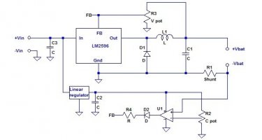
They were mostly 4-cell packs and because our power system at the time was drastically underperforming - the new Nickel-Iron cells we'd bought the year before were only storing of the charge they were supposed to - I had to be very careful charging the laptop cells not to drain the house battery overnight. I also had only one tester, and in order to do 2 discharge tests per day I charged the cells separately. I was using LM2596 buck circuits with a constant-current control on them to do the charging, but I only had three - so to speed things up I was charging the packs up BEFORE separating them. they were mostly 8-cell 14.8V packs so charging them to 16.8V at 1A worked nicely. Testing the cell voltages before and during charging with a DMM I could find the bad cells quickly. What I found was that most cells even if they were discharged down to 0.5V would charge up and rejoin the rest of the pack within a few minutes having the same voltage as the rest of the pack and staying that way all the way to the top. If it was lower than 0.2V, though, it would probably be heavily self-discharging and would get hot instead of charging. In the end more than 85% were usable.
I could test 8 cells every 12 hours so it took a month to get them all tested, taking time off for bad weather. I decided to keep the welded copper strips (these were OEM batteries probably from a company fleet being sold on) because I didn't see the point of throwing away connecting material only to replace it, and I wanted them as soldering tags so as not to heat the cells. But this meant that I couldn't use the plastic cell-holders that are so popular. I'd decided they were too expensive anyway (I'd looked on banggood and found that for the number of cells I had I'd need to spend more than 25% of the cost of the batteries, which seemed disproportionate to me - 50 compared to 180 for the batteries - I later found them for half that price on aliexpress but by then I'd already decided) so that didn't bother me.
I also had to find a way to do it with much less copper than others, since I couldn't find anything new or old with big solid copper wire in it here in Italy. I spent some time thinking about the 'standard' way everyone was doing it on youtube etc. with a heavy wire loop and connections on the end. I started doing somemath looking at how the voltages of the cells would differ under load, and decided that it really needed the heavy copper to work since it was such an ineffective way to do it. I didn't have the heavy copper (except for sheet copper from a roofing supplier) so I started from scratch. I had some thin plywood left from other projects and thought about tying cells to it with cable-ties - 2 pairs tied by two cable-ties. Then I wanted to fix the wires to the edges and decided that the least expensive way (though not the fastest) was to use short pieces of thin copper wire wrapped through holes in the plywood and over the top of the main connection wire, then soldered together to fix. The connection wire needed a connection loop and though I had thought about using sheet copper for this, in the end it was easier to just twist a loop into the wire. A 20cm7.5cm piece of plywood with 8 pairs of cells tied to it, 0.6mm wire making the negative connection and fine strands from some offcuts of microphone cable that I had tested to blow at about 5 amps forming fuses to the positive ends of the pairs forms one 'card'.


Because I was wanting the cards to all pass their current directly to the next one nearest to it, I decided they should all have equal capacity, so after sorting into 7 equal packs I then sub-sorted them all into equal cards, and then attached the larger 4 pairs in the centre (since they would carry proportionally more of the current as the packs were charged or discharged).
I was originally imagining longer cards hung from the top end on hooks or screwed to a wooden bar, but since I'd decided to subdivide the pack so far this no longer made sense and I thought about putting them on a shelf instead. The ends of the cards stuck out for fixing, so I designed a slotted shelf that they would slot into, made by attaching thin 4cm wide strips to a plank. The cards weren't stable in the slots so I thought about having a slotted lid, but after a while this felt too complicated and prevented removing single cards from the battery, so I decided to stabilise and fix them via their electrical connections. the attachment loops are small and maleable but it is easily secure enough once the copper strips it was screwed to are fixed at one end. The screws were small self-tapping types that can be simply screwed into the copper with a 2.5mm hole drilled, or screwed into wood.

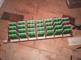
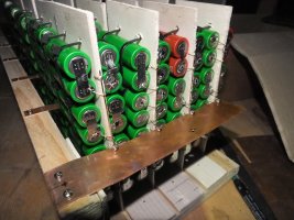
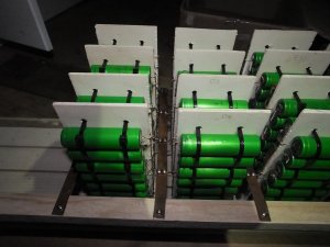
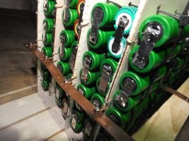

Then I attached it in place of the NiFe's and waited for it to charge. The cells were all at random, quite low charge levels (I always stopped the recharge part of the test cycle because we had so little stored charge and I wanted to keep testing every 12 hours) so some balancing was needed at first. I did this with some 3W 2.2? resistors (2 in series making 4.4?) putting them on the higher voltage layers to drop about an amp, till they came into line. I've been running them like this for a few months with no BMS (I'll make one soon) checking that things are still good every few days with my DMM and it hasn't needed balancing since. I have overdischarged it once (2 of the layers I had broken a fuse wire with my screwdriver during assembly so these ones ended up at about 1.5V) but it recharged and has been fine since, especially since soon after that I finished the second 7s80p since which our usage hasn't taken it down below 40% charged.
I have the PCM60X set to charge it to 28.3 which equates to about 4.05V/cell so there is some leeway. I also don't plan to take it much below 3.3V/cell, there's very little power down there anyway, and with these limits I hope the cycle life will be extended - though it will really only get a cycle when we have a long period of no sun, like 2 weeks, that we sometimes have 2 or 3 times a year. Since lithium cells have little to no calendar degradation this battery could last a very long time...
When I saw how much difference the first lithium battery made to our lives I immediately went and got 200 more laptop packs. I've processed 100 of these, a set from a German ebay seller which appear to be all from a replacement laptop battery company (Lavolta). Testing them they seem to be mostly new cells, and I got better than 95% good cells from this batch, making the 560 cells into a 7s80p with 5 cards per row in the same way as the first, except now I could use the charger to charge them since we had a power storage that actually stored power. But this was going slowly so I ordered 2 more of the same cheap charger (Litokala Lii500). I had felt that maybe there was some inaccuracy between the measuring bays of the first tester so when they arrived I started noting which bay of which charger each cell was charged in, and chose one cell-pair to re-test in every bay so I could see the differences. The differences turned out to be small, 2.5% on the discharge test and 2% on the charge (fast) test, although this amount of variation also turned out to be similar to the difference between a cold day and a very cold day.
When building the second battery I used my test results as a calibration to adjust the tested values according to which bay they were tested in. This turned out quite complex because I had to feed the adjusted values to the sorting algorithm and then seek back to the value written on the cell to actually find it. I did succeed in making a spreadsheet do this, and ended up needing to print 3 different sheets of figures to do the sorting. Trying to find each cells proper place from 35 different options wasn't easy! As I'd tested them I had taped them into bundles of 6 pairs and I'd entered the data in with these bundles as rows so as well as the table of cell values to row & card I also printed a "hint sheet" for each row saying which cards each cell in that bundle should go in, and a reference sheet for the hint sheet.



7 hours of sorting later I was ready to fix the cells to the cards and assemble the second battery, this time using M34mm screws into pre-tapped M3 holes in the copper strips, and I offset the screw holes along the copper strips instead of trying to fit them both in the width, but otherwise everything else was pretty similar.
The total cost of the materials to build this combined 7s144p pack was just 40. The batteries the cells came from cost 330. Total power storage (total of cell measurements) 8.2kWh.
cost breakdown:
Calculated for 7s144p in 2 stages: 7s64p & 7s80p
Money:
Item Qty Cost/ea Cost total
lead-free solder 240g 2.51 5.02
1mm wire 310m 1.99 5.97
0.6mm wire 117m 1.99 1.99
4mm plywood 46040 3 12
cable-ties 510 1.26 6.30
M3 screws 350 0.98 2.94
copper sheet 24cm*30cm 40/m 2.88
total 14.26 (=16.36)
total 22.84 (=19.91)
(rate 1=1.15 on 10th April 2018)
Combined Total 39.20 or 34.17
euro prices are the costs of buying these items locally, in supermarkets and diy stores. Sterling prices are from internet sellers (ebay and banggood)
Time: (not including pack dismantling and testing)
Action Hours
Cutting/Drilling Cards 3h (with knife not bandsaw)
Sorting 12.5
Attaching 12.5
Soldering 12.5
Base 2h
Cutting/Drilling Copper2h
Assembly 3h
Total 47.5h
I still have another 100 packs to dismantle, but I'm in no hurry now. Having attached that one below the first I am no longer even slightly worried about running out of power, even if the sun doesn't shine for a week, but I am planning to set up a fridge here for the first time this summer. Since I don't want an inverter running all the time for the fridge I'm going to set it up so that the fridges thermostat switches the inverter (next step would be a 24V DC compressor fridge, but they're super-expensive) for which I'm going to get a cheap chinese inverter just big enough to start the induction motor in the fridge. I don't care too much if it breaks, I'll just rebuild it better...
We currently have a lot of legacy 12V stuff, since for many years we ran only a 12V system. We still have 12V lead acid running our two inverters (400W for small loads, 3000W for tools etc.) so a step-down was needed for that. I also run a 35V system round the house and a 50V system down network wires to outlying buildings. All of this is done via non-isolating DC-DC converters that can be left on permanently because their quiescent current is just a few milliamps. They are also all based on high-quality toroidal inductors which means they put out very little EMR and because none of them have fans there is never any noise. I've put more details in another thread.
The 12V system has a monitoring system which I built myself from an arduino (pro micro) and a raspberry PI a few years ago. I plan to rebuild this system for monitoring the 7s lithium battery as well as everything else by using an stm32duino (maple mini clone) attached to 185V differential inputs in place of the pro micro. The design of this is already complete, I just need to get started with making it. Attached to this, for balancing purposes, will be a 7-way transformer based regenerative balancing circuit that I will also build myself, capable of up to 6-amps of balancing current. The whole BMS I expect to cost me less than 30, though writing the program for it may take a few weeks.
This is mainly an introduction to my system. It is a work in progress and I will update this thread as I do more.
I have some unusual system requirements.
I don't live in a house, though we have a house we don't live in. Compared with a normal house-based lifestyle my electrical power requirements are quite low, but there's no Grid power here up this mountain and sometimes the sun disappears for weeks, and we prefer not to use generators and petrol powered tools like chainsaws etc.
We've been making our own power for more than ten years now, though when we started with solar we just had a 100W solar panel and a leisure battery. Before that we just had a phone charger in the car and nothing else. So we've lived without, decided it's good, but have since decided to bring some technology back into our lives. Slowly building up what we really want into our life.
We understand the health problems caused by standard electrical installations. I don't want to live in the middle of a giant oscillating electromagnet so I keep everything DC as much as possible, and where conversion is required use converters with low emissions. Especially important is during sleep, so everything must become electrically quiet at night. This is why I live beyond the grid.
I came late to the Lithium party because my experiences (mainly with laptops) of lithium cells longevity was pretty disappointing. Why spend time, money, effort, on something that would fail in a year or two? I already had enough of that with the lead-acid batteries we'd been using (none have lasted more than 3 years - it's impossible with many users and only solar charging to maintain appropriate charge in a lead battery) but with the information and experiences of many lithium builders I could see that it could be quite different, and worth an experiment. So I bought a batch of 80 laptop batteries and a cheap tester, and got started with opening them to see what was inside.
They were mostly 4-cell packs and because our power system at the time was drastically underperforming - the new Nickel-Iron cells we'd bought the year before were only storing of the charge they were supposed to - I had to be very careful charging the laptop cells not to drain the house battery overnight. I also had only one tester, and in order to do 2 discharge tests per day I charged the cells separately. I was using LM2596 buck circuits with a constant-current control on them to do the charging, but I only had three - so to speed things up I was charging the packs up BEFORE separating them. they were mostly 8-cell 14.8V packs so charging them to 16.8V at 1A worked nicely. Testing the cell voltages before and during charging with a DMM I could find the bad cells quickly. What I found was that most cells even if they were discharged down to 0.5V would charge up and rejoin the rest of the pack within a few minutes having the same voltage as the rest of the pack and staying that way all the way to the top. If it was lower than 0.2V, though, it would probably be heavily self-discharging and would get hot instead of charging. In the end more than 85% were usable.
I could test 8 cells every 12 hours so it took a month to get them all tested, taking time off for bad weather. I decided to keep the welded copper strips (these were OEM batteries probably from a company fleet being sold on) because I didn't see the point of throwing away connecting material only to replace it, and I wanted them as soldering tags so as not to heat the cells. But this meant that I couldn't use the plastic cell-holders that are so popular. I'd decided they were too expensive anyway (I'd looked on banggood and found that for the number of cells I had I'd need to spend more than 25% of the cost of the batteries, which seemed disproportionate to me - 50 compared to 180 for the batteries - I later found them for half that price on aliexpress but by then I'd already decided) so that didn't bother me.
I also had to find a way to do it with much less copper than others, since I couldn't find anything new or old with big solid copper wire in it here in Italy. I spent some time thinking about the 'standard' way everyone was doing it on youtube etc. with a heavy wire loop and connections on the end. I started doing somemath looking at how the voltages of the cells would differ under load, and decided that it really needed the heavy copper to work since it was such an ineffective way to do it. I didn't have the heavy copper (except for sheet copper from a roofing supplier) so I started from scratch. I had some thin plywood left from other projects and thought about tying cells to it with cable-ties - 2 pairs tied by two cable-ties. Then I wanted to fix the wires to the edges and decided that the least expensive way (though not the fastest) was to use short pieces of thin copper wire wrapped through holes in the plywood and over the top of the main connection wire, then soldered together to fix. The connection wire needed a connection loop and though I had thought about using sheet copper for this, in the end it was easier to just twist a loop into the wire. A 20cm7.5cm piece of plywood with 8 pairs of cells tied to it, 0.6mm wire making the negative connection and fine strands from some offcuts of microphone cable that I had tested to blow at about 5 amps forming fuses to the positive ends of the pairs forms one 'card'.


Because I was wanting the cards to all pass their current directly to the next one nearest to it, I decided they should all have equal capacity, so after sorting into 7 equal packs I then sub-sorted them all into equal cards, and then attached the larger 4 pairs in the centre (since they would carry proportionally more of the current as the packs were charged or discharged).
I was originally imagining longer cards hung from the top end on hooks or screwed to a wooden bar, but since I'd decided to subdivide the pack so far this no longer made sense and I thought about putting them on a shelf instead. The ends of the cards stuck out for fixing, so I designed a slotted shelf that they would slot into, made by attaching thin 4cm wide strips to a plank. The cards weren't stable in the slots so I thought about having a slotted lid, but after a while this felt too complicated and prevented removing single cards from the battery, so I decided to stabilise and fix them via their electrical connections. the attachment loops are small and maleable but it is easily secure enough once the copper strips it was screwed to are fixed at one end. The screws were small self-tapping types that can be simply screwed into the copper with a 2.5mm hole drilled, or screwed into wood.


Then I attached it in place of the NiFe's and waited for it to charge. The cells were all at random, quite low charge levels (I always stopped the recharge part of the test cycle because we had so little stored charge and I wanted to keep testing every 12 hours) so some balancing was needed at first. I did this with some 3W 2.2? resistors (2 in series making 4.4?) putting them on the higher voltage layers to drop about an amp, till they came into line. I've been running them like this for a few months with no BMS (I'll make one soon) checking that things are still good every few days with my DMM and it hasn't needed balancing since. I have overdischarged it once (2 of the layers I had broken a fuse wire with my screwdriver during assembly so these ones ended up at about 1.5V) but it recharged and has been fine since, especially since soon after that I finished the second 7s80p since which our usage hasn't taken it down below 40% charged.
I have the PCM60X set to charge it to 28.3 which equates to about 4.05V/cell so there is some leeway. I also don't plan to take it much below 3.3V/cell, there's very little power down there anyway, and with these limits I hope the cycle life will be extended - though it will really only get a cycle when we have a long period of no sun, like 2 weeks, that we sometimes have 2 or 3 times a year. Since lithium cells have little to no calendar degradation this battery could last a very long time...
When I saw how much difference the first lithium battery made to our lives I immediately went and got 200 more laptop packs. I've processed 100 of these, a set from a German ebay seller which appear to be all from a replacement laptop battery company (Lavolta). Testing them they seem to be mostly new cells, and I got better than 95% good cells from this batch, making the 560 cells into a 7s80p with 5 cards per row in the same way as the first, except now I could use the charger to charge them since we had a power storage that actually stored power. But this was going slowly so I ordered 2 more of the same cheap charger (Litokala Lii500). I had felt that maybe there was some inaccuracy between the measuring bays of the first tester so when they arrived I started noting which bay of which charger each cell was charged in, and chose one cell-pair to re-test in every bay so I could see the differences. The differences turned out to be small, 2.5% on the discharge test and 2% on the charge (fast) test, although this amount of variation also turned out to be similar to the difference between a cold day and a very cold day.
When building the second battery I used my test results as a calibration to adjust the tested values according to which bay they were tested in. This turned out quite complex because I had to feed the adjusted values to the sorting algorithm and then seek back to the value written on the cell to actually find it. I did succeed in making a spreadsheet do this, and ended up needing to print 3 different sheets of figures to do the sorting. Trying to find each cells proper place from 35 different options wasn't easy! As I'd tested them I had taped them into bundles of 6 pairs and I'd entered the data in with these bundles as rows so as well as the table of cell values to row & card I also printed a "hint sheet" for each row saying which cards each cell in that bundle should go in, and a reference sheet for the hint sheet.


7 hours of sorting later I was ready to fix the cells to the cards and assemble the second battery, this time using M34mm screws into pre-tapped M3 holes in the copper strips, and I offset the screw holes along the copper strips instead of trying to fit them both in the width, but otherwise everything else was pretty similar.
The total cost of the materials to build this combined 7s144p pack was just 40. The batteries the cells came from cost 330. Total power storage (total of cell measurements) 8.2kWh.
cost breakdown:
Calculated for 7s144p in 2 stages: 7s64p & 7s80p
Money:
Item Qty Cost/ea Cost total
lead-free solder 240g 2.51 5.02
1mm wire 310m 1.99 5.97
0.6mm wire 117m 1.99 1.99
4mm plywood 46040 3 12
cable-ties 510 1.26 6.30
M3 screws 350 0.98 2.94
copper sheet 24cm*30cm 40/m 2.88
total 14.26 (=16.36)
total 22.84 (=19.91)
(rate 1=1.15 on 10th April 2018)
Combined Total 39.20 or 34.17
euro prices are the costs of buying these items locally, in supermarkets and diy stores. Sterling prices are from internet sellers (ebay and banggood)
Time: (not including pack dismantling and testing)
Action Hours
Cutting/Drilling Cards 3h (with knife not bandsaw)
Sorting 12.5
Attaching 12.5
Soldering 12.5
Base 2h
Cutting/Drilling Copper2h
Assembly 3h
Total 47.5h
I still have another 100 packs to dismantle, but I'm in no hurry now. Having attached that one below the first I am no longer even slightly worried about running out of power, even if the sun doesn't shine for a week, but I am planning to set up a fridge here for the first time this summer. Since I don't want an inverter running all the time for the fridge I'm going to set it up so that the fridges thermostat switches the inverter (next step would be a 24V DC compressor fridge, but they're super-expensive) for which I'm going to get a cheap chinese inverter just big enough to start the induction motor in the fridge. I don't care too much if it breaks, I'll just rebuild it better...
We currently have a lot of legacy 12V stuff, since for many years we ran only a 12V system. We still have 12V lead acid running our two inverters (400W for small loads, 3000W for tools etc.) so a step-down was needed for that. I also run a 35V system round the house and a 50V system down network wires to outlying buildings. All of this is done via non-isolating DC-DC converters that can be left on permanently because their quiescent current is just a few milliamps. They are also all based on high-quality toroidal inductors which means they put out very little EMR and because none of them have fans there is never any noise. I've put more details in another thread.
The 12V system has a monitoring system which I built myself from an arduino (pro micro) and a raspberry PI a few years ago. I plan to rebuild this system for monitoring the 7s lithium battery as well as everything else by using an stm32duino (maple mini clone) attached to 185V differential inputs in place of the pro micro. The design of this is already complete, I just need to get started with making it. Attached to this, for balancing purposes, will be a 7-way transformer based regenerative balancing circuit that I will also build myself, capable of up to 6-amps of balancing current. The whole BMS I expect to cost me less than 30, though writing the program for it may take a few weeks.
This is mainly an introduction to my system. It is a work in progress and I will update this thread as I do more.


