combining power supply units?

100kwh-hunter

Active member
Joined
Mar 2, 2019
Messages
1,374
As the title stating...

Is it duable/can it be done to combine several of my psu's together?
One is spitting out 6.3v at 30a, one is spitting out a 20A at 5.5. one is even spitting out 12v 70A (combined with several 12v) and some smaller ones

Or go back to there core (before regulating) at~15 up to 30v dc
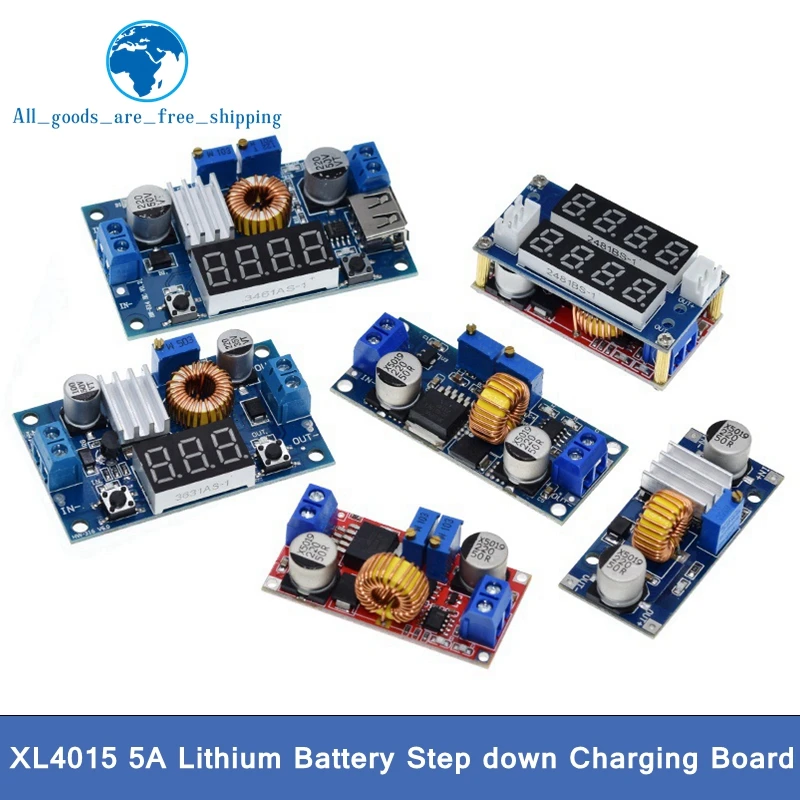
The end goal is to make a line that could provide 3.65v at the max A(hopefully 100A+) with the help of some dc dc step down converters

Or connect the line after the output of the dc dc step down converters.
I hope my jibberjad will make some sens?
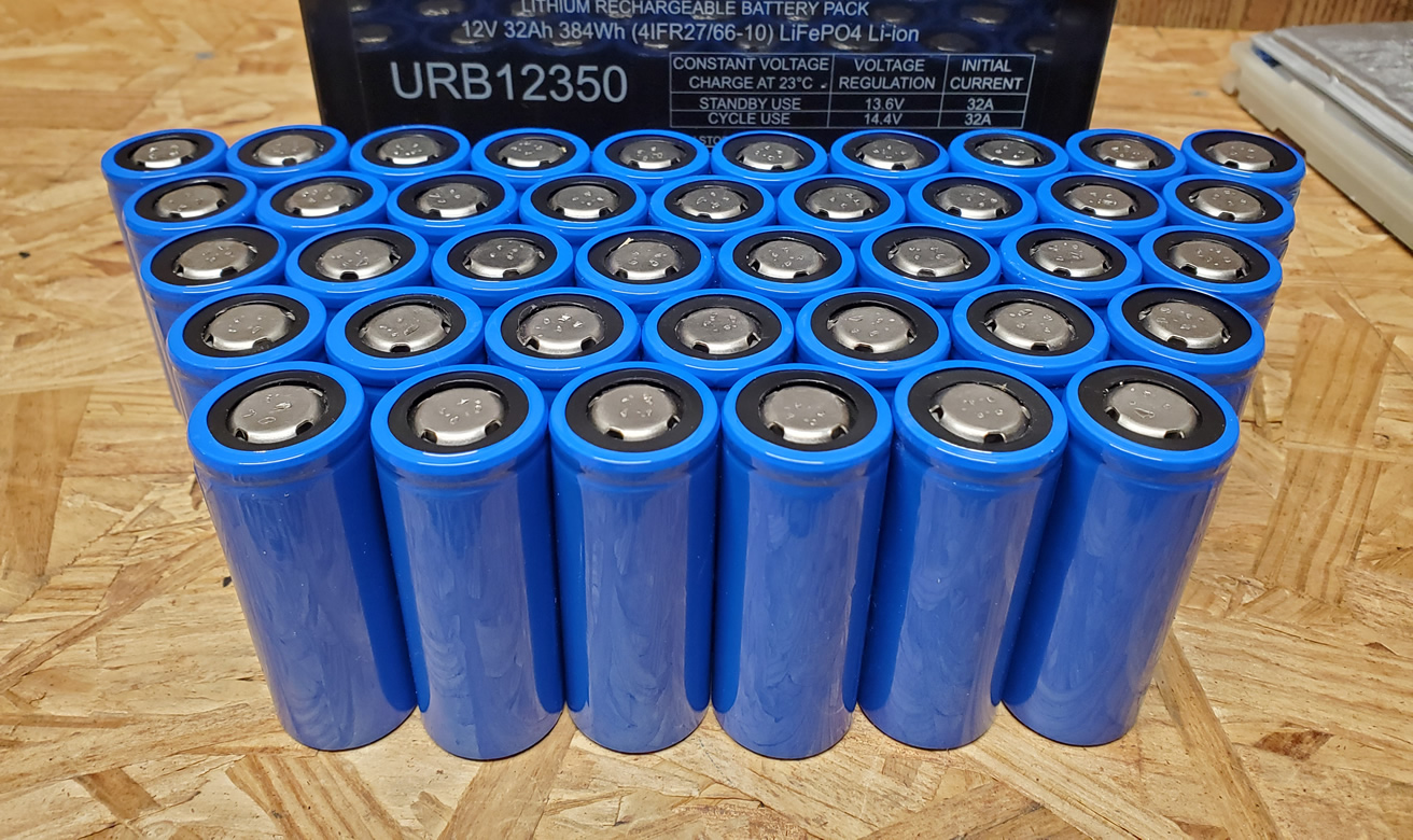
I am expecting to receive some lifepo4 cells (96 total)from china, i would like to charge them as fast as possible, to discharge as fast as possible, in accordance of the 7 to 15 day buyer protection.
I have a lot of powerful psu, really a lot and really powerful, not the chinees stuf rated.

Any help or thought is appreciated,
With best regards Igor

Ps with line i think i mean a bussbar, i could be wrong?
 
Yeah, you can connect PSU's together in series. Altho, some may not like to be connected as such. Depends on how the output is regulated.

The amperage limit will be the lowest output, though. Unless you parallel several together.

So you could take the 12V + 6.3V + 5.5V to get 23.8V, or there abouts. Always losses somewhere. But your current output will be limited to 20A.

However, if you bucked the 12V & 6.3V down 5.5V and then paralleled them, you'd get 5.5V @ 120A or so, and then you can boost that back up to 30V @ 22A, as long as the buck converter can do that. More like 20A as there's losses, of course.

Is it a good idea to do it? Probably not. Will it destroy equipment? It's a possibility.

Unless I'm missing your design question.
 
Im curious to hear about the result with PSU's. I did the same thing with smaller power supplies, series connected 2 identical 12V supplies to try to get 24v. Short answer is that it didn't work, output was all over the place with both voltage and current, and they shortly died. I don't know enough to know what causes fluctuating voltage.
 
output was all over the place with both voltage and current,
It's possible they were Switch Mode PSU's. They have a built in flyback circuit to detect the voltage/amps to keep things regulated. By putting the them in series with another unit, the sensing circuitry would see the wrong values, try to correct itself, and the values swing the other way, it recorrects itself, and keeps doing this. If the voltage ends up going over the rating of the equipment, it'll blow something up. Or the FETs will burn out from constantly working overkill.

This is probably why things went south. Dump PSU's, the ones with transformers in them, shouldn't have this problem though.
 
Is it a good idea to do it? Probably not. Will it destroy equipment? It's a possibility.

Unless I'm missing your design question.
@Korishan thank you very much for you replay.
Btw all of my psu are transformer based, all old fashion, metal and heavy.

Hmmmmm
To be on the safe side i made a schets/schematic, to give an impression:

20220407_075637.jpg

The psu's can be everything those are the 3 most strongest
I forgot to draw:
6v is 30A
15v is 20a
12v is 60A
But i have a few more....

The dc/dc is going to be:
And some of 20a:
I am putting those at 75% of there value at a psu, aka 30A psu 2x 20a dc/dc converter.
Or all 5A and up to 5A extra per psu? aka 20A psu and for 25A of dc dc converters?
I am open for suggestions btw.

Thanks in advance.
With best regards Igor

Ps the ac line has a fuse of just 16A
 
The negative line of the output has to be isolated, otherwise you will just short them out... not all power supplies are fully isolated. Some can ground the negative output with earth as well, so even though they may pass the AC through an isolation stage (high frequency transformer) the output can end up back with a common link.
Neither of those power supplies you showed have an isolated output. They regulate the current through a shunt on the negative return line.
With the current regulation being on the negative line, when you add them in parallel the current regulation is not balanced and unable to balance, so what can happen is one unit turns on and works and the other just sits at zero... or all hail the magic smoke...
 
The negative line of the output has to be isolated, otherwise you will just short them out...
Not sure that makes any difference with this current configuration. Tho it would be recommended to be further safe.

The psu's can be everything those are the 3 most strongest
I forgot to draw:
6v is 30A
15v is 20a
12v is 60A
As long as all power supply input is parallel, then Ground will always be 0-V reference. I didn't know that @100kwh-hunter was meaning that all outputs from the transformers would go into a DC-DC converter so that all outputs would be 3.65V.
The issue here is that the current output is limited by the converters, not just the transformers. As long as the converters can handle the amp throughput that the transformers can output, then the combined amps on the final output will be a sum of all the converters outputs.
 
Another option would be to use these if you have some higher voltage PSU units or they are isolated (putting the PSU output in series)...
They have isolated outputs and stack as many as you want in parallel, the 12V versions also voltage regulate at maximum output current.
I have used Cisco PSU units before (50V output at over 100A) as they are cheap (but inefficient) option and have isolated output.
This is the 6kW version https://www.ebay.co.uk/itm/124397165469 and they do 3kW ones as well. I think I bought mine for about £20 each a few years ago.
Just depends on how much power you want to play with.. lol.
These are the 1.2V versions. https://www.aliexpress.com/item/1005003491588734.html
 
Last edited:
Back
Top