

You are using an out of date browser. It may not display this or other websites correctly.
You should upgrade or use an alternative browser.
You should upgrade or use an alternative browser.
Communication between BYD Battery and Kostal Plenticore Inverter
- Thread starter Simon2021
- Start date

Engineer34
Member
- Joined
- Feb 5, 2020
- Messages
- 37
I am also curious. UP.
huntworker
Member
- Joined
- Feb 16, 2021
- Messages
- 39
Hi, I was also curious about the communication. And since I have both in my basement I did some measurements but still trying to decode.
I attached some short file of the log.
What I found out so far:
I have also more logs (charging from 20% to 100%, switch off Battery, switch on Battery).
Greetings and good luck for the TO for Wednesday")
I attached some short file of the log.
What I found out so far:
- all messages are ending with 0x00 (seen in the logic analyzer)
- there are 4 different length of messages. One are beginning with 0x09, another with 0x08 and others. The length also differs between the 4 types but is constant over time.
- If I switch off battery there is no more communication but Kostal is still on -> Battery is RS485 master?
- When I switched on the battery (while Kostal inverter is on), I can see immediately some data
- 12 V supply for the battery board is coming at least partly from Kostal inverter.
- Baud: 57600
- Data: 8
- Parity: none
- Stop: 1
I have also more logs (charging from 20% to 100%, switch off Battery, switch on Battery).
Greetings and good luck for the TO for Wednesday
Attachments
Hi, huntworker.
If I understand you correctly, the messages should look something like this:
I thought it might be a MODBUS RTU communication, but I can't find any known patterns. So probably is some proprietary format, and I'm suspecting an additional encoding. All these numbers 01,03,08,09,0A,00, etc. maybe are some special codes.
OK, I need to puzzle some more time...
What is the model of your BYD battery?
If I understand you correctly, the messages should look something like this:
Code:
0A E2 FF 02 FF 29 10 D8 81 43 01 07 8D 43 33 33 9F 41 01 01 01 01 01 01 01 01 01 03 48 42 01 03 C8 41 01 03 A0 41 01 07 90 41 CD CC 80 41 01 08 50 40 64 3B 4F 40 FA 02 01 02 14 01 01 02 C7 00
09 62 FF 02 FF 29 53 03 1F 00
08 E2 FF 02 FF 29 06 EF 00
09 62 FF 02 FF 29 4A 04 27 00
I thought it might be a MODBUS RTU communication, but I can't find any known patterns. So probably is some proprietary format, and I'm suspecting an additional encoding. All these numbers 01,03,08,09,0A,00, etc. maybe are some special codes.
OK, I need to puzzle some more time...
What is the model of your BYD battery?
huntworker
Member
- Joined
- Feb 16, 2021
- Messages
- 39
Hi,
exactly, these are the messages.
The 3rd, 4th and 5th bytes are all the same in all the type of messages during the whole day.
For the short messages, the first byte is the length of the frame, but not for the long frame (64 byte).
If you have any glue for the pattern you can tell it to me and I can compare it to my longer recordings. Or I can share all my logs via PM.
I have a BYD B-Box HV, so the old version (before HVM and HVS) with 6.4 kWh.
I think that the long frame contains the battery parameters. I still don't have any glue for the pattern, but there is one guess for message splitting:
The "01" is maybe some delimiter, and the next byte is the length of the segment, and then comes some data. But how data is encoded, I still don't know. We have to see how these numbers compare to major battery parameters (voltage, current, SOC, etc.) and how they change in the long run.
Code:
01 07 8D 43 33 33 9F 41
01 03 48 42
01 03 C8 41
01 03 A0 41
01 07 90 41 CD CC 80 41
01 08 50 40 64 3B 4F 40 FA
01 02 14
01 02 C7
The "01" is maybe some delimiter, and the next byte is the length of the segment, and then comes some data. But how data is encoded, I still don't know. We have to see how these numbers compare to major battery parameters (voltage, current, SOC, etc.) and how they change in the long run.
huntworker
Member
- Joined
- Feb 16, 2021
- Messages
- 39
New log from just the moment
And just have a look for the last message
Run Data has been
The run Data and the messages might not match 100% but they are pretty close taken from RS485 and the BYD installer website.
Code:
0A E2 FF 02 FF 29 62 90 85 43 01 0F 8D 43 9A 99 99 41 CD CC 6C 40 5B 8F 72 40 01 03 48 42 01 03 C8 41 01 03 A0 41 01 10 8C 41 9A 99 81 41 54 E3 55 40 68 91 55 40 FB 02 01 02 28 01 01 02 C9
0A E2 FF 02 FF 29 21 90 85 43 01 0F 8D 43 9A 99 99 41 33 33 73 40 A5 70 6D 40 01 03 48 42 01 03 C8 41 01 03 A0 41 01 10 8C 41 9A 99 81 41 54 E3 55 40 68 91 55 40 FB 02 01 02 28 01 01 02 10
0A E2 FF 02 FF 29 BE 8F 85 43 01 0F 8D 43 9A 99 99 41 33 33 73 40 32 33 73 40 01 03 48 42 01 03 C8 41 01 03 A0 41 01 10 8C 41 9A 99 81 41 54 E3 55 40 68 91 55 40 FB 02 01 02 28 01 01 02 1E
0A E2 FF 02 FF 29 42 90 85 43 01 0F 8D 43 9A 99 99 41 CD CC 6C 40 5B 8F 72 40 01 03 48 42 01 03 C8 41 01 03 A0 41 01 10 8C 41 9A 99 81 41 54 E3 55 40 68 91 55 40 FB 02 01 02 28 01 01 02 E9
0A E2 FF 02 FF 29 42 90 85 43 01 0F 8D 43 9A 99 99 41 CD CC 6C 40 CE CC 6C 40 01 03 48 42 01 03 C8 41 01 03 A0 41 01 10 8C 41 9A 99 81 41 54 E3 55 40 68 91 55 40 FB 02 01 02 28 01 01 02 3F
0A E2 FF 02 FF 29 3B 8F 85 43 01 0F 8D 43 9A 99 99 41 33 33 73 40 A5 70 6D 40 01 03 48 42 01 03 C8 41 01 03 A0 41 01 10 8C 41 9A 99 81 41 54 E3 55 40 68 91 55 40 FB 02 01 02 28 01 01 02 F7
0A E2 FF 02 FF 29 0C 92 85 43 01 0F 8D 43 9A 99 99 41 33 33 73 40 32 33 73 40 01 03 48 42 01 03 C8 41 01 03 A0 41 01 10 8C 41 9A 99 81 41 54 E3 55 40 68 91 55 40 FB 02 01 02 28 01 01 02 CD
And just have a look for the last message
Code:
0A E2 FF 02 FF 29 0C 92 85 43
01 0F 8D 43 9A 99 99 41 33 33 73 40 32 33 73 40
01 03 48 42
01 03 C8 41
01 03 A0 41
01 10 8C 41 9A 99 81 41 54 E3 55 40 68 91 55 40 FB 02
01 02 28
01
01
02 CD
Run Data has been
Code:
ArrayVoltage: 267.127
PackVoltage:  267.820
Current:      3.782
SoC:          40.600
SysTemp:      19.3
MaxCellVolt:  3.342
MinCellVolt:  3.337
MaxCellTemp:  17.5
MinCellTemp:  16.2
MaxVolPos:    3
MinVolPos:    1
MaxTempPos:   1
MinTempPos:   4

TotalChargeEnergy: 1890.622
TotalDischargeEnergy: 1610.508
TotalCycleCount: 251
The run Data and the messages might not match 100% but they are pretty close taken from RS485 and the BYD installer website.
huntworker
Member
- Joined
- Feb 16, 2021
- Messages
- 39
And if 0x01 is some delimiter, how is make sure that it is not into data?The "01" is maybe some delimiter, and the next byte is the length of the segment, and then comes some data. But how data is encoded, I still don't know. We have to see how these numbers compare to major battery parameters (voltage, current, SOC, etc.) and how they change in the long run.
Roland W
Member
- Joined
- Oct 9, 2017
- Messages
- 146
Just a quick question from a communications noob... why does an inverter need to talk to the battery?
Everything it needs to know, it can (and i guess every hybrid inverter does have a basic functionality) find out by metering at its battery terminal.
That would be voltage and current.
What else would make that combo be more effective if they are communicating? Or is it just about displaying more stuff on each other displays?
Are there any brand inverters, which would not work together with other brand components because there is no communication link?
I just saw from a SolArk inverter for example, if you don't have comms to the battery, it would not display you some information on its battery info page, but else just work as normal...
Last edited:
huntworker
Member
- Joined
- Feb 16, 2021
- Messages
- 39
Hi Roland,
there is no possibility to set up the battery into the inverter. There are no voltage limits or current limits in the inverter.
So the battery tells the inverter the current SoC and the allowed charge and discharge currents.
This is pretty standard for consumer inverters.
there is no possibility to set up the battery into the inverter. There are no voltage limits or current limits in the inverter.
So the battery tells the inverter the current SoC and the allowed charge and discharge currents.
This is pretty standard for consumer inverters.
huntworker
Member
- Joined
- Feb 16, 2021
- Messages
- 39
New Log at 100% soc:
Code:
0A E2 FF 02 FF 29 6F 52 86 43 01 03 8D 43 01 03 A0 41 01 01 01 01 01 01 01 01 01 03 48 42 01 03 C8 41 01 01 01 01 01 10 A0 41 9A 99 91 41 EE 7C 57 40 2B 87 56 40 FB 04 01 40 64 01 01 02 58
0A E2 FF 02 FF 29 48 51 86 43 01 03 8D 43 01 03 A0 41 01 01 01 01 01 01 01 01 01 03 48 42 01 03 C8 41 01 01 01 01 01 10 A0 41 66 66 92 41 EE 7C 57 40 2B 87 56 40 FB 04 01 40 64 01 01 02 E6
Code:
ArrayVoltage: 268.621
PackVoltage:  268.450
Current:      0.026
SoC:          100.000
SysTemp:      20.000
MaxCellVolt:  3.367
MinCellVolt:  3.352
MaxCellTemp:  20.000
MinCellTemp: 18.200huntworker
Member
- Joined
- Feb 16, 2021
- Messages
- 39
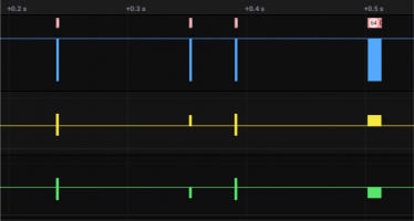
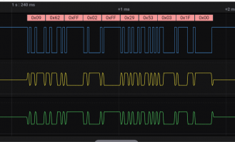
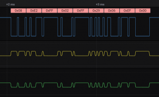
Attached some Screenshots from the Measurement.
Overview: 4 Messages every ~1 sec
OnePacked: Zoomed in into one bunch of 4 Messages
DetailFramex: Each message in detail. Here you can see the different participants. The first and third frame is more RS485 like while the second and fourth is more CAN like.
Overview: 4 Messages every ~1 sec
OnePacked: Zoomed in into one bunch of 4 Messages
DetailFramex: Each message in detail. Here you can see the different participants. The first and third frame is more RS485 like while the second and fourth is more CAN like.
Attachments


@huntworker, nice sniffing! What device do you use to log the data?
I think I catch it
The parameters are encoded as 32-bit floating numbers. I've used this online calculator to convert the data. So let's start decoding. I will use your previous frame that corresponds to 40.6% SOC.
The first four bytes are some constants, so we will ignore them:
In the next section we have four 32-bit number, but the first one is not fully encoded:
And the remaining bytes:
I'm not sure for date encoding here. Maybe 0xFB->251 is cycle count, and 0x28 is 40% SOC.
You may try to decode some other frames to verify my findings.
I had a good brainstorm this evening
I think I catch it
The parameters are encoded as 32-bit floating numbers. I've used this online calculator to convert the data. So let's start decoding. I will use your previous frame that corresponds to 40.6% SOC.
The first four bytes are some constants, so we will ignore them:
Code:
0A E2 FF 02 FF 29 0C 92 85 43 -> 0x4385920C -> 267.14V (battery voltage)
Code:
01 0F 8D 43 9A 99 99 41 33 33 73 40 32 33 73 40
8D 43 -> 0x438D000 -> 282.0V (max charging voltage from datasheet)
0x419999A -> 19.2 deg (sys temp)
0x40733333 - 3.8A (battery current)
0x40733332 -3.8A (battery current again ?)
Code:
01 03 48 42 -> 0x42480000 -> 50.0A (max discharge current ?)
01 03 41 C8 -> 0x41C80000 -> 25.0A (nominal discharge current )
01 03 A0 41 -> 0x41A00000 -> 20.0A (max charge current ?)
Code:
01 10 8C 41 9A 99 81 41 54 E3 55 40 68 91 55 40
8C 41 -> 0x418C00000 -> 17.5 deg (max cell temp)
0x4181999A -> 16.2 deg (min cell temp)
0x4055E354 -> 3.342V (max cell voltage)
0x40559168 -> 3.337V (min cell voltage)
Code:
FB 02 01 02 28 01 01 02 CDYou may try to decode some other frames to verify my findings.
I had a good brainstorm this evening
Last edited:
huntworker
Member
- Joined
- Feb 16, 2021
- Messages
- 39
These are very good news!
I did't had in mind to view this in in float values. I had been so fixed into fixed-point values.
Good Job!
sometimes "01 0F" comes to "00 00" but next time "01 03" is used for "00 00" and the next time it is "01 10" for "00 00".
. But we will clarify this by this week.
Thank you again for this great work!
I will give you some pictures of my setup tomorrow.
And I will start to write a small application to calculate the values live currently I am streaming the raw data via WiFi to my PC. MOre on that tomorrow.
For all those who cannot wait:
I can imagine that the MaxVolPos and MaxTempPos are displayed as Bit-Array. More on that as well tomorrow.
I did't had in mind to view this in in float values. I had been so fixed into fixed-point values.
Good Job!
I will do some more logs to see if they are really constant over time. This might also be a version of the string -> constant or maybe the time?The first four bytes are some constants, so we will ignore them:
I am still curios about the "00" because this is a not allowed char.8D 43 -> 0x438D000 -> 282.0V (max charging voltage from datasheet)
sometimes "01 0F" comes to "00 00" but next time "01 03" is used for "00 00" and the next time it is "01 10" for "00 00".
That was also in my mind, but I hope that the cycle count can be higher than 255, otherwise the battery will be useless in the next few days.0xFB->251 is cycle count,
. But we will clarify this by this week. That will be easy to find out.0x28 is 40% SOC
Thank you again for this great work!
I will give you some pictures of my setup tomorrow.
And I will start to write a small application to calculate the values live currently I am streaming the raw data via WiFi to my PC. MOre on that tomorrow.
For all those who cannot wait:
Code:
0A E2 FF 02 FF 29 CF 77 82 43 01 0F 8D 43 66 66 A2 41 66 66 E6 BF 46 E1 DA BF 01 03 48 42 01 03 C8 41 01 14 A0 41 CD CC 9C 41 CD CC 8C 41 FE D4 50 40 75 93 50 40 FC 02 01 02 3F 01 01 02 B4
Code:
Current: -1.775
SOC: 63.000%
SysTemp: 20.300
MaxCellVolt: 3.264
MinCellVolt: 3.260
MaxCellTemp: 19.600
MinCellTemp: 17.600
MaxVolPos: 3
MinVolPos: 4
MaxTempPos: 1
MinTempPos: 4Korishan
Administrator
- Joined
- Jan 7, 2017
- Messages
- 7,538
Considering @huntworker and @Simon2021 are coming from the same place, perhaps you can share the information and try out the solutions on each others devices.
huntworker
Member
- Joined
- Feb 16, 2021
- Messages
- 39
Unfortunately we are talking about the same device. I talked to my brother about this and he started this thread. I just hijacked it.Considering @huntworker and @Simon2021 are coming from the same place, perhaps you can share the information and try out the solutions on each others devices.

But if anyone has access to a different device, I might provide my setup.
I will have access to a Plenticore Plus 7.0 with an 7.7 kWh HVS and to a Plenticore Plus 8.5 with an 5.1 kWh HVS beginning of April. I will record the data as well and hope that they will be similar to the old HV series.
huntworker
Member
- Joined
- Feb 16, 2021
- Messages
- 39
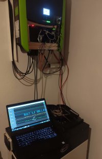
It is time to show you my setup.I will give you some pictures of my setup tomorrow.
First I need to tell you that I am an electrical engineer working in automotive industry. I develop control units for human machine interfaces for several OEMs. With that I have knowledge about several communication interfaces, so it was no problem with my equipment to sense for the protocol and voltages on the bus.
Basically I just used my Saleae Logic Analyzer which hast analog and digital channels.
With that I could measure the voltages (CAN vs RS485), baudrate, start- and stop bits, parity, packet lenght and the 00 delimiter.
In the second step I needed to translate the bus voltages into PC readable levels. For that I used the CAN transceiver of an outdated control unit. The transceiver is a TJA1043 from NXP, which was just available, you might also take the classical used SN65HVD230, but I do not like them because they are less robust than the automotive stuff. ^^
With the output of the transceiver I had standard UART levels which I could read with a USB to UART converter. Thats where the first messages and logs came from.
The last step was to stream the data via wifi. For this I used an ESP8266 board which is readable with netcat over tcp. Tricky part was that the data are streamed as raw hex which needs to be translated in ASCII representation.
Next step is to write a small program to read the raw data and show it as human readable numbers. For that it would be interesting to get a hint for the representation of a 0x00 byte. This happens somehow with an 0x01 byte.
Attachments


@huntworker, nice setup!
Also, I think "01" marks the start of a segment, followed by its length. The length byte is included in the total length.
For example:
We have four FP numbers here (one in the "short" form): 2+3*4+1 = 15 (0F)
If we follow the same logic here:
Again 2+3*4+1 and remains "FB" byte, which must be a part of this segment. But as you mentioned is a little strange to encode the cycle counter in one byte.
I guess "00" is a special symbol, so the number 0x438D000 is encoded as 0x438D, and the zeroes are omitted.Next step is to write a small program to read the raw data and show it as human readable numbers. For that it would be interesting to get a hint for the representation of a 0x00 byte. This happens somehow with an 0x01 byte.
Also, I think "01" marks the start of a segment, followed by its length. The length byte is included in the total length.
For example:
Code:
01 0F 8D 43 9A 99 99 41 33 33 73 40 32 33 73 40If we follow the same logic here:
Code:
01 10 8C 41 9A 99 81 41 54 E3 55 40 68 91 55 40 FBhuntworker
Member
- Joined
- Feb 16, 2021
- Messages
- 39
Both confirmed. Current cycle count is 253, so we will get an answer the next days. Maybe there will be bytes inserted?Maybe 0xFB->251 is cycle count, and 0x28 is 40% SOC.
Code:
FF 02 FF 29 C5 60 85 43 01 07 8D 43 9A 99 A5 41 01 01 01 01 01 01 01 01 01 03 48 42 01 03 C8 41 01 01 01 12 CD CC B0 41 66 66 9E 41 06 81 55 40 DF 4F 55 40 FD 04 01 40 64 01 01 02 D6
Code:
01 01 01 12Do you think all the 00 will be exchanged by 01. But what happens with the real 01?
Korishan
Administrator
- Joined
- Jan 7, 2017
- Messages
- 7,538
Unfortunately we are talking about the same device. I talked to my brother about this and he started this thread. I just hijacked it.
But if anyone has access to a different device, I might provide my setup.
Glad that was cleared up. Usually when several new users show up with same address location they are spammers. Just checking to make sure things are all good