dis/charger/tester

100kwh-hunter

Active member
Joined
Mar 2, 2019
Messages
1,374
I am going to build a dis/charger/tester, does this count as a project? for this section of the forum?
With the knowledge i accumulated around here, ofcourse.
If not, please delete this post, thanks in advance.

With best regards, Igor
 
Last edited:
Hey,
Me too. Wanted to try and make an analog correcting CC discharge circuit and us a Raspberry Pi 3b as the controller.
Plan on using the TP5100 modules for charging.

Just waiting for parts.
 
My project was started some weeks ago.
I am planning to make a dis/charger tester to spit out every aspect of a cell in one go by using simple electronics and simple logica.

So far i have done testing the psu what is working and what is not working and why.
I have done some testing on those charging chips and discharging units.
See other posts of mine.
So its time to start with the build.
I chose a different approach because i dont like to take the cells in and out there holder.
The cells must "walk" between different stages of charging and discharging and testing, to get a decent figure of what there capisity is and remaining life left.
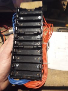
First the built of the bay's, i dont know if this is the proper name for it? suggestions are welcome,

Sorry i did not make any pics from my saw table, forgot.

As mentioned before i am a carpenter by trade, so dont look to close at the wood work :angel:
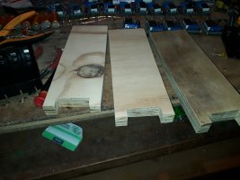
image_ghauld.jpg


I made several of those, time to get the sticky stuff on it, there are not much glue brands that will stick on that plastic cell holders
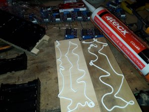
image_uwvlxj.jpg


image_jexabl.jpg


image_paboxy.jpg


image_fuclec.jpg


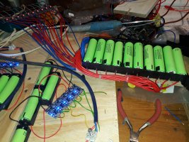
Time to solder some

image_vpkhkz.jpg


image_wxlalc.jpg


image_mqqsti.jpg


I am going to add some sensors that will lite up a led when one is getting to hot.
That safety feature will get a own power line.

Why so much? I will charge them first and wait one week to check on the volt, then they will be on the board.
As the project wil form i will post more pictures and info.
This dis/charger tester is designed to do threethings, in one go, SOH% plus capacity, with ir in one go,30 cells a day when i am home after workand not a sleep.


Sorry, the bay with the screws in them was the prototype. they dont have any screws in them.
The sensor must still be added, and the wire's are 0.75mm and even in length, oke they will be at max 3mm in difference in length
 
For those thermistors are some free hole's left in the plug where i can solder some extra wire onto.
If i going to proceed with sensors, big if.
The sensor itself is going to be inside the cell holder(corner in the middle) so every cell will get his own sensor.

My first option was a sensor that let no power thru under the 40c and let power thru above 40 degree, break than make.
To power up a led.
But i can't find those sensors anymore, out of production?

My second option would be a ntc/ptc resistor with the same principle.
Third option, would be those sensors that you find in the packs that you are harvesting.

My third option require some electronics, and i wanted to keep it simple: cell cold no led burning.
Cell above 40 degree led burning.
With the 5 volts from the same power supply, maybe with a little help with a step up or step down converter to feed some electronics.

To keep cost low( i will be needing a 120!) and things safe, i will only test when i am at home, and feel every half an hour or so.
Heaters can be quickly discovered by touch, you just need to encounter one.

Thanks in advance for any hint/trick or help with those sensors.

Meanwhile the project build is getting into a good shape, i will post picture's this weekend of what i was doing the last two weeks.
 
Good idea about triggering an LED. Just requires manual monitoring. It will save you time over an IR thermometer or the "hand test." You could even attach it to a relay to cut off charging when a temperature cutoff gets exceeded. I really like the idea of reusing laptop BMS thermistors because there is no additional cost or waste.
 
I was thinking about some relay's, would be to costly, or i have to start all over again to get them into the board.
I changed the design two times.......but at the bright side, i am pretty happy now.
But the relay(correct me if i am wrong) switch back when the temperature is going back to normal.

So i am still trying to find out what will work, the wish is indeed to trigger a LED.
Must be very simple, with a minimum on electronics, but how, what is a good idea?
Somehow those BMS thermistors dont work without extra electronics.

Thanks
 
Some build up dates.
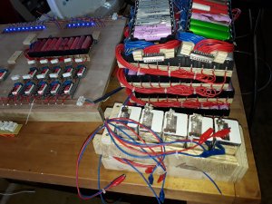
Thingy is getting together.
Everything was tested

Still a lot of soldering to do and a lot of wires to connect.


image_dzzmhj.jpg


image_eunkqf.jpg


image_yywzlh.jpg


image_qwabaq.jpg


image_fwcejv.jpg


image_yiwjqn.jpg


best
 
You are right, the relay would return power after the temperature dropped. I'm not an Electical Engineer, but I'm sure there is some low tech way to cut power to the circuit and not turn back on until manually reset. Like I said in the beginning, it seems really complicated to add temperature sensing without adding a lot of complexity.
 
Small update.

Still waiting for my IR meter, Kelvin method.

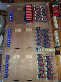
Finished a lot of soldering, including 13units, 6 for on the bays and 7 spare, for every day one.
The units for those gp cells are still not done. planning to finish them this weekend

image_wpwpuq.jpg

The wires in the units for the gp's are connected that way, that they will receive the double amount of charging and discharging.
10 amp cells, got a lot of them.

image_cabrag.jpg


It's time for the first test run.
The first bay is empty because i charged them last month.
And i burned 15 of those chips, dont ask me how...stupid mistake
The oldest onethat was charged is in the second bay.
The second bay is for checking if they are still above 4.11v and to discharge them to 3.8v
SD will be taking out and the slow sdwill go fora second run(back into the "fresh pile" with a marking on it), in case they need to "wake up"
If the second run also shows a slow sd its out.

image_dectkt.jpg


When this is done, that unit will go to the third bay to charge up to 4.2v and a other one will go into the second one.


image_hvxdcd.jpg


Best


I tested all those tc's and zb's on proper voltage, the testing was posted on this forum.
Incl power supply
Sorry i dont know how to post alink.
The tc's and zb's that where out of range are in bay number six and seven.


Best
 
day 3
Working good so far.
The units moved up one bay and the first unit is now in bay four.(red sanyo)
Bay four is for testing the actual soh%
Discharge from 4.2v(yesterday) to 2.8v
Already two drop outs, 2100mah cells give back 1030 mah, so i would say 50% life left.

image_bfvohj.jpg


Added a new unit on the board (in thesecond bay)and that unithave two sd's
I marked them as sd and will be taking out at the end and go to the sd pile.

image_mdwtqy.jpg

Every day the unitswill move up a spot, so the chemistrycan settle between each "task".

All the cells that not make it in the first test run, will be tested later again, lets see if there are cells that had to wake up.
Incl heaters, dead, sd, 40-60soh% and 60-80soh%
Where heck is that rubber boat from china with my ir meter?

Best
 
1050 mAh is not 50 % life left, it is 95 % life spent. You would not use these i a parallel block together with better ones.
 
setup for tomorrow

image_rqqvne.jpg


To sum it up:
Bay one: charge fully and check for heaters,let them rest for a week, planning to make more units for two weeks.
Bay two: after a week check for (slow) sd and discharge to 3.8v.
bay three: charge full up again.
Bay four: discharge full range with the manufacture recommended discharge load.(see the resistor bank on it) to get the remaining capacity and thus the soh%
Bay five: charge again
Bay six: discharge to 3.5v for storage

So every day 10 - 30 fullytested cells.
That is it for now.
Project costs for what is on the board.

13x2 & 26x4Carprie holding boxes: 32e
30x zb's: 75e
30xtc's: 8e
20x d sub connectors: 8e
180 meters of 1mm wire 36e
50 Resistors: 5e
total: 164euro
Psu i already had in my shed.
Wood was from my work for free.

Amount of beer wasted, not able to calculate :huh:

Next upcoming project:test board for those who give trouble, sd's, heaters, low on soh, wake up's and "dead" cells

Best


@ cherry67.
Thats why i am testing, to get those ones out, and get the good ones in the wall
But if half of the original capacity is left, that mean 5% life left, instead of 50%?

Thanks for the heads up

Best
 
Hey there, curious what you mean by zb's and tc's? They must be the display boards and resistors or something, since I see 30x of those. Nice DIY setup!!
 
Back
Top