DIY Arduino based 1-16 channel cell discharger/datalogger

Elmo

Member
Joined
Feb 19, 2017
Messages
189
I've built an Arduino UNO based cell discharger and written the software to control it and send the data to a PC. With the UNO up to six A/D converter channels are available, only had parts for four channels at hand but have ordered the relay card and the lamps for the other two channels. Using the Arduino Mega 2560 you can have up to sixteen channels discharging at the same time. I have the parts to build a 16 channel version in my cart at Amazon and they are currently under $60.

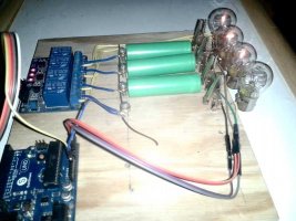
I have used 1156 12V taillight bulbs as loads for the individual cells, these draw 1.17A@4.2V, 1.08A@3.6V and .99A@2.90V, they are a great choice for discharging laptop and other cells.

After I wrote the software I realized I was basically datalogging so not only can the device act as just a discharger but the entire voltage vs time curve is available to be entered into Excel or whatever spreadsheet for analysis.

Anyhow, it is said that a picture is worth a thousand words so here..


image_rnhgrm.jpg


image_ikxffg.jpg


image_jrxovi.jpg
 
I usually don't draw a schematic for simple things like this. I'll draw something up and post an image.

An Arduino will measure 0-5V to 10 bits precision or roughly 5mV, just connect the voltage to the 'duino pin and give the read command.. A little math for conversion and there you are. Don't try to measure anything over 5V though or bad things can happen.

You can also do 1.1V to about 1mV precision by giving a command to change the reference voltage.
 
This is proper DIY :)
 
daromer said:
This is proper DIY :)

Thanks, I appreciate that.

Be aware there is no reverse voltage protection for the Arduino, put a cell in backwards and that channel is most likely gone and possibly the entire thing.

Like you said, proper DU.. I mean DIY. Prone to emitting smoke signal in event of operator error. :)
 
Elmo said:
I usually don't draw a schematic for simple things like this. I'll draw something up and post an image.

An Arduino will measure 0-5V to 10 bits precision or roughly 5mV, just connect the voltage to the 'duino pin and give the read command.. A little math for conversion and there you are. Don't try to measure anything over 5V though or bad things can happen.

You can also do 1.1V to about 1mV precision by giving a command to change the reference voltage.

Thanks :) Sounds very simple...!
 
Anyhow, it is said that a picture is worth a thousand words so here..

Well, I think just one word. NICE!!!! :D

Looking forward to the code/layout as well. I've been thinking of ways to do this. Ideas are one thing, putting it down on traces is another. Just starting in the circuitry territory.
 
Code... Haven't got around to the schematic yet...


Code:
float timevalue, current, elapsed, analogvalue5, voltage, milliamphours, cutoffvoltage, finalmah, slope,lastvolt;
float analogvalue, vcell1, vcell2, vcell3, vcell4;
int dacount, lock1, lock2, lock3, lock4;
void setup()
{
 Serial.begin(9600); //turn on serial monitor
 pinMode(8, OUTPUT); // enable pin 8 for output, just change the number for other available pins
 pinMode(9, OUTPUT);
 pinMode(10, OUTPUT);
 pinMode(11, OUTPUT);
 digitalWrite(8, HIGH); // turn off relay connected to pin 8 and may need to be reversed for FET control
 digitalWrite(9, HIGH);
 digitalWrite(10, HIGH);
 digitalWrite(11, HIGH);
 delay(10000); //delay ten seconds for oops time and uploads
 digitalWrite(8, LOW); // turn on relay connected to pin 8 and may need to be reversed for FET control
 digitalWrite(9, LOW);
 digitalWrite(10, LOW);
 digitalWrite(11, LOW);
 lock1=0; // these hold the final mah value for each cell
 lock2=0; // set when voltage goes below threshold 
 lock3=0; 
 lock4=0;

}


 int getanalogvalue() //    function to read A/D, takes "dacount" modifies "voltage"
{
 for(int x;x<5000;x++) // this loop gets the analog value of A/D (X) 5000 times and adds it to itself
  {
 
   analogvalue=analogvalue+analogRead(dacount);
 
  } 
 analogvalue=analogvalue/5000; // averages the A/D value
 voltage=analogvalue*0.005664;  // calculates voltage from A/D value
}
 
 ///////////////// start main program ///////////////////////////

void loop()
{
 cutoffvoltage =2.8; // Your cell cutoff low voltage goes here
 delay(7800); // Delay to slow down the readout and make it more legible
         // updates every ten seconds or so with this number
 analogvalue=0;
    
 dacount=1; // gets the cell voltage and stores it..one for each channel
 getanalogvalue();
 vcell1=voltage;

 dacount=2;
 getanalogvalue();
 vcell2=voltage;
 
 dacount=3;
 getanalogvalue();
 vcell3=voltage;

 dacount=4;
 getanalogvalue();
 vcell4=voltage;
  
 elapsed=millis()/1000; // calculates seconds since program started
 Serial.print(elapsed);
 Serial.println(" seconds discharging");
 milliamphours=elapsed*.297; // use this number for a Sylvania 1156L 12V lamp as a load for one cell,
                // different lamps will require different numbers
 
 Serial.print(vcell1);
 Serial.print("   ");

 Serial.print(vcell2);
 Serial.print("   ");

 Serial.print(vcell3);
 Serial.print("   ");

 Serial.print(vcell4);
 Serial.println(" Voltage ");
 
 //Serial.println(); 
 
 if (vcell1<cutoffvoltage) //makes the decision to cut off off if below threshold
 {
  if (lock1==0)
  {
   lock1=milliamphours;
  } 
   
  digitalWrite(8, HIGH); //turns off relay and may need to be reversed for FET control 
  }

  if (vcell2<cutoffvoltage)
 {
   if (lock2==0)lock2=milliamphours;
  
  digitalWrite(9, HIGH); 
  }
  
 if (vcell3<cutoffvoltage)
 {
   if (lock3==0)lock3=milliamphours;
  
  digitalWrite(10, HIGH); 
  }

 if (vcell4<cutoffvoltage)
 {
   if (lock4==0)lock4=milliamphours;
  digitalWrite(11, HIGH); 
  }
 
 if (lock1>0)
  {
  Serial.print(lock1);
  Serial.print("   ");
  }
  else
  {
  Serial.print(milliamphours);
  Serial.print("  ");
  }

   if (lock2>0)
  {
  Serial.print(lock2);
  Serial.print("   ");
  }
  else
  {
  Serial.print(milliamphours);
  Serial.print("  ");
  }

   if (lock3>0)
  {
  Serial.print(lock3);
  Serial.print("   ");
  }
  else
  {
  Serial.print(milliamphours);
  Serial.print("  ");
  }

   if (lock4>0)
  {
  Serial.print(lock4);
  Serial.print("   ");
  }
  else
  {
  Serial.print(milliamphours);
  Serial.print("  ");
  }
 Serial.println("  Milliamphours");
 if (lock1>0 && lock2>0 && lock3>0 && lock4>0)
  {
   
   Serial.println();
   Serial.println("Done discharging");
   
   while(1){}
  }
 
 }
 
Here's why I didn't bother drawing a schematic.. I don't know any schematic software and my motor skills aren't what they used to be.

It's this circuit repeated however many times, once for each cell.

There is a digital ground that goes to each relay card as well as a +5V, there are up to eight relays on a card so ten lines altogether from Arduino to card. Two eight gang relay cards will give you sixteen channels of data.


image_tqmroc.jpg


Relay card... https://www.amazon.com/gp/product/B00KTELP3I/ref=ox_sc_sfl_title_1?ie=UTF8&psc=1&smid=A28RI4FXFS5SV8

Generally digital I/O pins can sink more current than they can source so energizing a coil by taking the output pin low is the way it's often done, these relays have a optoisolator built in but the concept is the same, drive the LED in the opto on by taking the output low and off by going high.
 
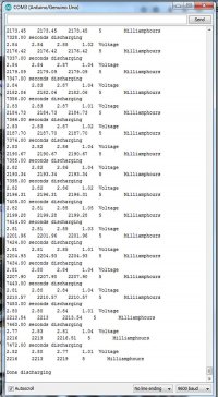
Attaching a text file of the program output for Rerouter.
 

Attachments

  • discharged cells number 1.txt
    91 KB · Views: 300
Elmo said:
Attaching a text file of the program output for Rerouter.

wish you had included temperatures, but here is the first chunk of derived math, and i agree some of those functions look scary, but they are much easier to implement in C,

The Delta Mode so far looks to be the best indicator of apparent capacity, the mode value of how many seconds it takes to drop by 1mV
 

Attachments

  • battery calcs.xlsx
    419.1 KB · Views: 300
That's quite interesting.. Here's another run with the same cells but I didn't get them in the same order, I wanted to see if the channels read the same but my charging leaves something to be desired in accuracy. I suppose I'll have to build a charger next.

I briefly tried to put a "slope" function in that gave the millivolts per time period drop but I had messed up something and kept getting values that didn't make any sense and I was tired so I cut it out...

If you scroll through the data you can see the difference between the top and bottom voltage in the window, I was using that as the data came in and it gave me an idea of the slope of the curve at any given moment.

All the cells I have on hand for testing are either new or nearly new 25R cells or cells that I already retired from ebike service so they are less than stellar. Nothing in between at the moment and I won't have time to do anything with newer cells for a month or more.

I only have one temperature sensor at the moment. With an Arduino Mega I could do eight channels of voltage and eight of temperature.

How did you get the ESR out of that data?


Oh, one other thing, the current declines slightly with voltage, not linearly by any means but it's about 1.17A @ 4.2V and .99A @ 2.9V, I could give you set of say 10 measurements from 2.8 to 4.2 if that would be helpful.
 
Elmo said:
That's quite interesting.. Here's another run with the same cells
I briefly tried to put a "slope" function in that gave the millivolts per time period drop
I only have one temperature sensor at the moment. With an Arduino Mega I could do eight channels of voltage and eight of temperature.
How did you get the ESR out of that data?


Oh, one other thing, the current declines slightly with voltage, not linearly by any means but it's about 1.17A @ 4.2V and .99A @ 2.9V, I could give you set of say 10 measurements from 2.8 to 4.2 if that would be helpful.


Think you forgot your attachment,

The slope function is, if the voltage from the last reading is lower by 0.01V or more, store this timestamp, subtract the last timestamp where it occured to get the time, then divide the difference in voltage by this value, The mode function is the statistical center value, as such it ignores the noise around the edges, and is more telling than the average, I then recipricated this value and divided it by 1000 to get a number that was easier to tell the fitness at a glance

I would only need 1 temperature sensor to derive the data, I am just in need of like the ESR in the previous one, some numbers to determine fitness of the math

I pulled the ESR out at your termination voltage, see how the current falls to 0, and then the voltage bounces back, to delimit noise i made it so it only tried calculating ESR when the voltage was 0.05V higher than the previous, and then as the current fell 1 reading before termination, i used the current of the reading before on the assumption its going to be a very similar delta, (from what i can tell, you measure voltages, then afterwards currents, which causes an odd current readingwhen you stop discharging)

The discharge current was derived from increase in capacity Vs time, its showing what your system measured, at least averaged over those time periods
 
Didn't forget so much as screwed it up... Still not used to this forum software.

I'll see about adding ambient temperature reading then... I already have code for that it's just a question of adding it without borking anything else.

Also it's evident that continuing the the readout for a bit after the final cell is discharged will be helpful, I'll see about that too.


I think you have a misunderstanding, I'm using the characteristics of the 12V bulb I'm using as a load to infer the average current through the cell and then calculating an assumed milliamphour value from that.

The characteristics of the bulbs are very similar, within the limits of my measuring apparatus to tell the difference, that's one reason I swapped the cells around in the second test to see if the results were significantly different from one channel to another.

I can make a fairly accurate current sink, I can make four with one cheapo and uber common analog IC but I'm trying to keep this hardware as simple as possible and put the sophistication (such as it might be) in software.
 

Attachments

  • discharged cells number 2.txt
    90.3 KB · Views: 318
Elmo said:


I think you have a misunderstanding, I'm using the characteristics of the 12V bulb I'm using as a load to infer the average current through the cell and then calculating an assumed milliamphour value from that.

The characteristics of the bulbs are very similar, within the limits of my measuring apparatus to tell the difference, that's one reason I swapped the cells around in the second test to see if the results were significantly different from one channel to another.

I can make a fairly accurate current sink, I can make four with one cheapo and uber common analog IC but I'm trying to keep this hardware as simple as possible and put the sophistication (such as it might be) in software.


image_jksuzp.jpg

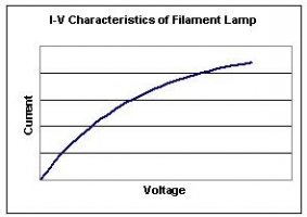
Seems like your assuming your globes pull a constant current independent of the voltage, which isvery unlikely, you likely will want to measure the Voltage vs current of your globes to actually describe the function, then your assumptions should be within single digit% error,

Your current sinks / Sources dont need to be that fancy, just start cleaning up the assumptions that are easy to remove,
Also thosetemperature readings, I was hoping for an Ambient, and a single cell in direct contact, just to simplify the math,

The other thing that would make calculating ESR easier would be if it turned off for a second or 2 each voltage step, measured the rebound in voltage, then turned back on and continuing, but an ESR curve is more a 1 off curiousity i am after data on, As it would allow predicting the wattage lost each charge and discharge cycle,
 
Here's the data points on the current draw for the bulbs from 4.5V to 2.5V


Code:
4.5,1.17
4.4,1.17
4.3,1.15
4.2,1.14
4.1,1.12
4.0,1.11
3.9,1.09
3.8,1.08
3.7,1.07
3.6,1.05
3.5,1.04
3.4,1.03
3.3,1.01
3.2,1.00
3.1,.98
3.0,.96
2.9,.95
2.8,.93
2.7,.92
2.6,.90
2.5,.88


And here's an equation I came up with that fits the points fairly well, you can probably do better I'm as rusty as the Tin Man after a monsoon at this.

y = 0.3056364 + 0.2615152*x - 0.01515152*x^2

I'll put the math in the Arduino code to calculate and display an actual mAh reading, if you come up with better fitting equation let me know.

How about a two second load cessation for each cell every 100mV?


Keep in mind this started out strictly as an ad hoc project built with stuff I already had laying around or easily removed from other things to measure relative capacity for harvested cell binning. Now it's turned the corner into scientific research it will take me a bit to adjust my mindset.

Edit: Found a better fit.

y = 0.4263977 + 0.2081818*x - 0.009469697*x^2
 
Back
Top