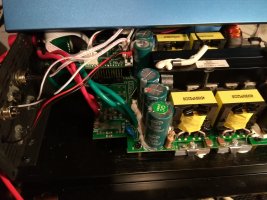
External limiting an GTIL2 SUN-1000G2 with raspberry

daromer said:
Tocan: Ah ok. No idea which one of the groups are the genuine. I have talked to some one there that said was the management before and they told that they would think about adding the controll point of the feed back to the rs232 as well and not just the pot or the display settings

Hi just to let you know... I work good together with their developer.

And he implement this feature for me as far i understand you both in the right way correct. The problem his english is not good and my knowledge is far from to be reasonable specialin electronic terms in english.

His answer:
Yes, the firmware can set the parameter of the device, sucn of control the output.

Is this you did mean?

See do you plan to buy soon you can send me a PM. Maybe i can make a good price. Special for shipping. I have a brand new unit. But its the small one 45-90V with 1000 Watt.

My plan was to send it to developers to have the unit local and after they use it ship me back... Principle of the 1000 Eyes...
 
How you are going on? I will get the modbus description for gtil on monday in english language. I did mention them To set it under CC-BY-SA License. On Thuesday i get their official Wifi dongle.
 
Are there any updates on this?

I am using these inverters and have a need to externally control the target wattage.

I'm willing to buy new ones if they are doing hardware updates, or whatever else I need to make them work.

Right now I'm ready to test with a pretty good powerwall setup and I've been using one of their inverters for a little while now without any dynamic control.
 
Yes i got a second inverter and a Wifi dongle. Only the report is not clear. I requested to for free all to CC-BY-SA and i suggest for this than to use Wikipedia maybee. The package to sweden is ready and i know Daniel is busy Daromer did not answer anymore and so i thought he have no more interest in this topic or its not urgend. In general all is complete for deeper investigation.
 
So you should be able to control the output wattage over IP?

Does it take a new inverter or just the wifi dongle and/or firmware?

And can I update firmware on existing inverters? If not where did you buy the correct inverter w/ the newer firmware on it?

Thanks
 
Did you ever get the modbus documentation?

Even if it is not under the proper license it might be pretty easy to work out some of the important stuff.
 
I did posted here the chinese version inside the thread, you can put the content to google translate and be familiar. O my request they did translate on their own costs and i think its good to wait theirs manager decitions to free it. See i am in early state and their trust is more important than fast solutions. So if you can not wait please translate for yourself. Somewhere in this thread there is an attachment.
 
roland said:
I ordered the same GTIL (45-90V/1000W) and want to control the output power with a 0..5V or 0..10V signal to construct a home storage solution. Delivery of the GTIL is next week and for that reason all this writing is theoretically. I'll do practical tests in October. Maybe the input is a 0..20mA or 4-20mA input. You described that over 2.5V there is full output power. If there is a kind of optocoupler inside it could be that the forward voltage is around 2.5V with current limiting series resistor and then forward current is 20mA. Do you try out a input current like 0..20mA?

The third day I try to hackthe signal of an external limiter. Difficult, because I do not have and you have to manually select the signal.With the setting enabled, the external limiter was not able to get the value of extra power, which it displays under voltage.What I tried: sinusoidal signal with different voltage, filling, shift; a constant voltage from 0 to 30V (on the input there is an optocoupler and the main thing is not to exceed the current of 20-50mA, current limitation makes a 1k resistor on the board); PWM with different amplitude, frequency and duty cycle. The result is negative. :(
 
dakoal said:
I have a Battery
The GTIL2 is connected to this battery, and to the grid.

His "normal" function is to measure the powerflow from the grid to the house with the help of the blue clamp sensor and try to zero it with power from the battery.

If you have to phases in your house, you need 2 GTIL, if you have 3 phase (Austria, Germany ...) , you need 3 Inverters to zero out every phase.

With the modification I did, I can tell the GTIL how much power to feed into the grid on his one phase.
So I can feed the power consumption of all three phases to te grid and the meter stops.
Up to 950 Watts this works with a SUN1000 Gen2 without any problem.

First Video was showing "Pot" Mode, where you can mount a knob on the housing of the inverter and can set 0 to 100% power.
Second video shows the possibility to feed an external voltage (0-1,6V), for example produced with PWM from an Arduino or Raspberry to this pot port and also controll 0-100% power.

Is it now better understanding?

Have a great day

Hey Bernhard,

one question please:
Where did you feed in the 0-1,6V? I guess your voltagesupplie in the video on youtube has an isolated voltageoutput, right? You did not tied it to bat-gnd or even earth?


Regards


Carsten
 
After I received my GTIL it doesnt work with the 0..1.6V analog programming as described in bernhards post. Still wonder why? I need to tie the GND-Wire to Earth. With this additional connection as you can see in the pictures below the steering of the powerfeed to grid works. The funny thing is: I don't know why this connection ist necessary...


image_lbavor.jpg


image_ctofew.jpg


This is my simplified schematic for the PV-Battery (only in german actual, sorry) with prismatic LiFePO4 cells:

image_qzvafv.jpg


Almost all parts are working, so finally I need to do some software work to control the system. Because my experience in NI-Labview I will do the software in Labview.

image_nafxko.jpg


Some useful informations regarding my BMS you'll find at my blog about electric cars. I did some convertions of 2CV to electric cars and the battery and BMS technology is developed by myself.
http://elektrente.blogspot.de/

Best regards and a happy new year 2018!!!
 
I don't know if anyone is still pursuing the goal of controlling their GITL2 via the external limiter input, but I managed to pick up a used external limiter unit and have been analysing the signal and thought I would post my findings:

At first, I though it was a straightforward PWM signal, bit as I tried various different loads, it seems there is no correlation between the frequency/mark-space of the signal and the actual output power the inverter is generating.

The following table shows the signal at various output power levels:

Code:
Load Period mS Freq Hz Low mS Hi mS %
-----------------------------------------------------------
No load 6540 0.154 1120 5420 79.3
30W 640 1.562 476 164 34.4
60W 458 2.813 326 132 40.5
90W 320 3.125 234 86 36.7
120W 242 4.132 170 72 42.3
150W 448 2.232 356 92 25.8
180W 640 1.562 476 164 34.4

So, as you can see 30W and 180W produces exactly the same signal. After puzzling over that for a while, I started watching the signal as I changed the load and I think I have figured it out.

The image below shows the signal as I change the load from 50 to 100 and back to 50W. The limiter holds the line low for an extended period to demand more power and high to demand less (signal is inverted due to how I am monitoring it).


image_mgbveg.jpg


Once the correct output power level is detected by the limiter it goes back to some nominal frequency/mark.

So it looks like the limiter does not send an absolute output power request to the inverter, but instead sendsmore/less requests until the required output power
is achieved. In other words, it is some type of balanced feedback system.

Therefore, my Arduino solution is going to have to know the output power at all times in order to balance the output to the required level. So I will either need to add a CT clamp input, or use the serial Modbus interface to read the current output power level (have been translating parts of the Chinese spec @Tocan posed earlier, and it looks promising) in order to correctly mimic the signal.

Hmm, more complicated than I had hoped, but doable.

DANGER WARNING:
If anyone wants to replicate this experiment, please read below!

Before I event powered up the limiter unit I couldn't resist whipping the lid off to see how it worked (who doesn't to that :D ).
I was horrified by what I found. If I had connected the mains input to the terminal block, as per the label, one if the pins on the signal connector that goes to the inverter would have been 240VAC live mains!!!

Even if I assume the factory stuck the label on the wrong way around (which I think is the case since it also meant the L/N of the front sockets get swapped), that still leaves the neutral connected to one if the pins. That is just as bad, but perhaps not as lethal.

At best I could have blown up my oscilloscope and worst case electrocuted myself. This is only a low voltage signal (a few volts) to drive an LED in the opto-coupler inside the inverter. I have no idea why it is connected like this.

Anyway, I would recommend that anyone who has one of these external limiter units perform the following test:
1.Disconnect ALL wires.
2.Using a multimeter, perform a continuity test between the live/neutral connections and the pins on the limiter output connectors.

If there is continuity, then in my opinion it is not safe.

It is not for me so say what to do about it if yours is the same as mine, but I personally, would not use it or would modify it to make it safe.

Note also that the metal housing of the signal connector is not even earthed.

The image below shows my little opto-isolated breadboard setup allowing me to safely monitor the signal (I had the left half covered up whilst powered).
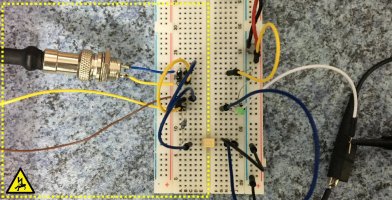

image_spdrxa.jpg


Sorry for such a long post but thought others may find it useful.
 
I'm interested in any updates as I am looking at these inverters.

I was told by the company that the external limiter signal was just a 0-5V linear signal, although it would appear from the earlier post that it is a PWM modulation of some form. 80% duty for no change and +/- for increase/decrease.

The external limiter box stated a 30m maximum cable distance and I was looking at a 4-20mA conversion for transmission. The RS485 method would be ideal if it has been implemented.....

From the earlier post with the 0-1.6V control this seems doable with a couple of 4-20mA converters for transmission and changing the voltage level.
PWM to Voltage : https://www.aliexpress.com/item/PWM-to-voltage-module-0-100-PWM-into-0-10V-voltage/32635902555.html
Voltage to Current : https://www.aliexpress.com/item/Vol...4-20mA-Linear-Conversion-H02/32797770858.html
Current to Voltage : https://www.aliexpress.com/item/Iso...nt-to-Voltage-4-20mA-to-0-5V/32823001896.html

Yep, not ideal to go PWM --> 4-20mA --> Voltage on a short hop....
 
Having done the above analysis, I now know how to go about designing a unit that will replace the external limiter and have the ability to take commands to set the output power of the inverter. However I am not ready to do that yet as I am currently designing my own bms and shunt monitor, after which I thenneed to build all ofmy cell packs and then connect and install them.
I am going with an ac coupled system and originally I was was going to use the external limiter as is.But I now have an OpenEVSEthat uses my spare solar power to charge my EV.
This means that it would conflict with the EV changing. So having the ability to control the inverter output is going to give me more options as to when a how I use my powerwall energy.

Is that the same sort of thing you guys are looking for?

@completelycharged: are you just loooking to extend beyond the 30M or for control as well?
 
I have "cable run" distance of around 45-50m or an ethernet connection distance of a few meters... I have to have data via cable at one end because wifi will not work.

My incomming metering point will have 6 CT with serial output which will go into a Pi so I have the flow data that I need to net off and the value to set the GTIL (or my solar inverter - still working a different option).

Looking at the previous post in relation to the 0 to 1.6V method and this is what I will do if the unit still does not support control via the serial port. The PWM looks a right pain and an odd way to implement the control method as it ill always result in a lag, but I suppose part of that is to stop oscillation if the metering data is relatively dumb and non time correlated / referenced.

The metering box they sell with the GTIL for the remote option just seems a bit excessive for what should be needed ?
 
completelycharged said:
I have "cable run" distance of around 45-50m...

If you can route your45-50m cable run away from any other cables to minimize any interference or cross talk it may be worth a try to see if it will work anyway without modification.

completelycharged said:
Looking at the previous post in relation to the 0 to 1.6V...

The 0 to 1.6v you see on the oscilloscopewas a result of theopto-coupler connection i used to safely monitor the signal. I suspect the actual signal will be at normal logic levels.

I think if I were trying to extend the range, I would transmit the signal asdifferentialusinga max 485 driver / receiver. I thinkthose things can reliably work over several km. That wil require a cable of at least three conductors though.

completelycharged said:
...if the unit still does not support control via the serial port.

I spent quit a while translating / studying the serial protocol and played around readingthe registers and came the the conclusion that there is no support for setting or reading theoutput power in real time.

completelycharged said:
The PWM looks a right pain and an odd way to implement the control method as it ill always result in a lag,but I suppose part of that is to stop oscillation if the metering data is relatively dumb and non time correlated / referenced.

I remember reading about this in the facebook group where is was suggested that, by design, the inverter ramps up/down over a small number of seconds to prevent ringing.
 
Huge, huge shame the serial port method does not work and a missed market opportunity for GTIL, very unfortunate.

There was an earlier post (10-01-2017, 05:58 PM ) that had a 0-1.6V voltage signal controlling the output from a 2 pin connector inside the inverter.

BTW, nice work looking at the PWM output with the scope.

In theory if the signal is PWM modulation at a low frequency and the signalling logic current draw is very small a larger size conductor cable (lower resistance) would work as long as there is not too much capacitance in the line. I was also looking for a way to save spending $40+ on a box, which I thought was not really needed. The separate 50m cable run would also be a right pain as I would have to dig up the garden again for 30m and the wife will not be happy.... I have 4 ethernet cables already burried and may look at using one of those for signalling...

Been thinking about the ringing/oscillation issue and if you can monitor all of the loads excluding the inverter and calculate the required output then oscillation/ringing should be near on impossible. There could be some very small ringing potential due to the change in line voltage but that should be very very small.

With the GTIL remote box approach they only monitor one point and the remote box does not even seem to know what the inverter is sending out and just blindly signalling more, more, more or less, less, less.. the PWM approach only makes sense to get some distance, but why did they not use use 4-20mA or the serial port ???
 
completelycharged said:
There was an earlier post (10-01-2017, 05:58 PM ) that had a 0-1.6V voltage signal controlling the output from a 2 pin connector inside the inverter.

Ah, I was a cross purposes.
I remember watching that video before and now realise I completely missed the subtleties of what was being demonstrated.
I now see that although he is using the external limiter connector to the outside world, he has moved the internal end from the yellow socket to the normally unused white one. I have just tried, and successfully replicated it.
So that is another option to pursue.

completelycharged said:
In theory if the signal is PWM modulation at a low frequency and the signalling logic current draw is very small a larger size conductor cable (lower resistance) would work as long as there is not too much capacitance in the line.

As far as I can tell, the pwm signal just drives a photo-coupler inside the inverter. In other words, just an IR LED.

completelycharged said:
.... I have 4 ethernet cables already burried and may look at using one of those for signalling...

You could certainly use one pair plus a ground for sending PWM via a RS485 driver.

completelycharged said:
Been thinking about the ringing/oscillation issue and if you can monitor all of the loads excluding the inverter and calculate the required output then oscillation/ringing should be near on impossible.

I'm not sure exatly what they meant by *ringing* in this context but I suspect they just mean that the inverter gently ramps up and down to prevent overreacting to sudden changes required to ensure zero export to the grid. So there will be small amounts of import/export during the transition periods.

completelycharged said:
With the GTIL remote box approach they only monitor one point and the remote box does not even seem to know what the inverter is sending out and just blindly signalling more, more, more or less, less, less.. the PWM approach only makes sense to get some distance, but why did they not use use 4-20mA or the serial port ???

The GITL was only designed to prevent locally generated energy from feeding the grid, andI think it fulfills that requirement very well.
We are trying to use it it a way it was not designed for, and so we are having to get creative to get it doing what we want.
 
Thanks for the info and help.

From what you have said through all the posts I'm comming to the conclusion the 1-1.6V route is the only viable way.

Agree with the photo-coupler the mA of the LED should be small enough not to cause any issues and the 4-20mA route would work as well with the slow PWM modulation you had in the earlier post image.

I think thier version of ringing is when the output is ramped up very quick and overshoots the target so then has to back off and then undershoots. Wihtout the inverter actually having a specific target rather than just an "increase output by 100W" signal it does make faster tracking an issue.

Will hopefully fit my CT's and monitors in the next couple of weeks so will see how this data would work with the unit.
 
Back
Top