External limiting an GTIL2 SUN-1000G2 with raspberry

Forgot to add.... the reason I was looking at the thread again is that it appears the main boards for the GTIL units are available on Aliexpress for half the price of a full unit, just lacking the heatsink, case, fan, display.... and then started to think if they could be controlled then all you need is the board...
 
I tried to write Register 40-42 but it seams they are read only?

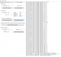
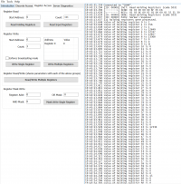
Screenshot2.PNG

Screenshot1.PNG
 
Just as a sense check (i may have digit pairs the wrong way round) is your unit serial number either 21012948 or 12109284 ?
If that matches your serial then the port your accessing is filtered and offset or input registers

Can you try a 0x04 read input register instead of 0x03 ? Guessing this will not work.

The curious bit is the non response to a register write.

I also thought I read in one post that there are two different RS485/serial access points and one has more privilage.

So, if this is a full port not going through a secondary device I wonder if a write to a particular address with a partiicular value would then unlock the port.... ?
 
Last edited:
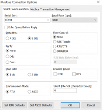
This are my modbus settings:
MOdbus Settings.PNG

My SN is:
SN.png

Reading Holding Register 4 gives me:
04:57:24.550 [ID: 00003] INIT: Read Holding Registers (code $03)
04:57:24.565 [-------->] SEND: 01 03 00 04 00 01 C5 CB
04:57:24.666 [<--------] RECV: 01 03 02 30 31 6D 90 00
04:57:24.666 [ID: 00003] DONE: Read Holding Registers (code $03)
04:57:24.681 [ID: 00003] PASS: Normal response
04:57:24.697 1 holding register was processed.
04:57:24.713 Value of holding register 4 is 12337

Reading Holding Register 3 gives me:
04:58:00.204 [ID: 00004] INIT: Read Holding Registers (code $03)
04:58:00.204 [-------->] SEND: 01 03 00 03 00 01 74 0A
04:58:00.319 [<--------] RECV: 01 03 02 32 31 6C F0 00
04:58:00.319 [ID: 00004] DONE: Read Holding Registers (code $03)
04:58:00.335 [ID: 00004] PASS: Normal response
04:58:00.351 1 holding register was processed.
04:58:00.366 Value of holding register 3 is 12849

I don't think that my modbus settings are wrong.
Reading Holding Register 70 (Grid Voltage) gives me 2264, which seams to be right (226.4V).

Never heard about a 2nd RS232 Port. Can you give me more information (i.e. Pinout?)
 
Looks ok in terms of data accuracy as the serial and other bits match up.

Within the protocol document there is a process flow diagram, which has no filtering for registers other than the valid 01-7D range (0x00-0x7C)

Only options I can think of are :
1. external port is purposefully firmware limited due to it being hooked up to an untrusted wifi signal and therefore a risk (understandable and would pose a certification risk for grid connection)
2. External port is switched to full mode via secret address and register value write
3. Secondary port exists (unclear as to the main center chip) which then has full access
4. Firmware is fully locked down and would otherwise need a jtag download and re-programming (or just one flag removing to say it is locked down ?).

The LCD route is an interesting one but I know my wind unit just connects the dump load while it reboots if you change any significant settings, so the issue with the output going to zero from a previous poster makes sense as the unit is internally booting back up.

The way that some of the registers are setup leads me to believe some, but not all methods of power control work without a reboot because otherwise the device would not work in the first place. This is why I was thinking register 40-42, but they are locked.
 
Does someone has experience with using these GTILs with already a existing invertor in the house/net ?
As seems they can't detect the current direction ...
When you set these on (activate, connect to the 230V) and there is already injection to the net (from the existing invertor), they see this as 'power used from the net' ( seen on the display )
I don't have my batteries yet, so can't test/see how they would react.
Would they finally detect it is injection and stop feeding the net ? ( as for example if 1000 W is injected by the other invertor and they want to compensate this the display reading would go to 2000 W ?)
Anyone knows ?
 
Hi, I found this page after looking for answers for doing the same thing. What people said here seems like it got way too complicated for me. I am planning on a way that seems more simple to me. Maybe it may be helpful to others that find this pages for same reason as me as well.
I am doing the following:
Clamp Current Sensor 100A/50ma ong each power line that go to an audio amplifier with 50ohm input resister that has differential input for signal isolation (signal isolation is a must to not get any cross over signal from other clamp current sensors, and differential inputs will also help reduce electrical noise), so that 100A = 2.5V AC, setting audio amp to approximately 0 to 2 gain so the output can be adjusted if needed to be 2.5-5V max AC (prefer around 4V to compensate for bridge rectifier diode voltage drop lost). Then convert that to DC with a bridge rectifier and capacitor with some resister (2K-4.7K range) across that capacitor to drain capacitor. Then using a four channel analog to digital converter module connected to a raspberry pi 3 near the power line clamp current sensor, and make a program to read each channel voltage and figure out what value to send over wifi network to other raspberry pi 3 next to inverter via either telnet or ssh or ftp or putty or some command line messaging. The raspberry pi next to inverter will listen for or read the value from the other raspberry pi monitoring the input power lines, and then with a program get that value and have code adjust the audio volume output and arrange for it to output a consistence 60hz sound that will go in to a class D audio amplifier with output of 2.5V max. Then that will go in to a 1 to 1 audio isolation transformer (signal isolation is a must in to internal limiter port or could get a ground loop problem making things go out of whack) that will go in to the internal limiter connection in to the inverter. This sill be like simulating the 60hz from the clamp current sensors on the power lines but through the wifi network using multiple raspberry pi 3 units. To mimic the power line clamp current sensor make a program to listen to or read from the power line monitoring raspberry pi 3 to tell what value it should be on the inverter limiter side and simply have the volume adjust to the desired value with a program code. I have 2 inverters at different locations and do not want to run a long wire though the house or over the house. So I will have two raspberry pi 3 listen or reading from the main power monitor raspberry pi 3 with 2 clamp current sensor to calculate what each inverter should do.
The RS485 serial communication for the external limit input is interesting but from what I gather the RS485 seems too complicated to figure out the protocol if not the manufacture, but would be nice if its figured out. Will be waiting to hear about that more.
 
I have been interested in this inverter for a while but neither have the tech knowledge neither I have it yet :) but my 2 cents on this:

- There is a repository in Github that allows mqtt over the inverter so you don't need to use the shinemonitor to monitor it. I believe there is also a mapping showing the registers. (https://github.com/TradeFace/modbusmqtt/issues/1)

- Also, a different inverter (Sofar), with the help of the modbus manual, allows to put the inverter in passive mode that allows to send instructions to control the charge or discharge rates of the battery (https://www.raspberrypi.org/forums/viewtopic.php?t=259427)

Keep us posted with any updates, really good job here.
 
hi folks,
I have created a small ESP32 program (https://github.com/BlackSmith/GFSunInverter), for reading data from an inverter. Benefit of this solution is it can be powered from the inverter (RS232 - pin 9 - 12V). I have ready PR into https://docs.openmqttgateway.com, for sending data to mqtt broker if someone looks for it.
Now I can identify these registers:
Code:
# Register:0 Value:2               ???
# Register:1 Value:256             ???
# Register:2 Value:1               ???
# Register:3 Value:12601           # device ID  2x chars
# Register:4 Value:12594           # device ID  2x chars
# Register:5 Value:12594           # device ID  2x chars
# Register:6 Value:12336           # device ID  2x chars
# Register:7 Value:14641           # device ID  2x chars
# Register:43 Value:12336          ???
# Register:59 Value:512            ???  // may be bit flags; this value is if inverter works
# Register:60 Value:2              # Custom Power  int16
# Register:63 Value:5752           # Total Power   int16
# Register:70 Value:2313           # AC Voltage  int16
# Register:86 Value:5340           # Average power int16
# Register:109 Value:601           # DC Voltage    int16

What I want to detect when the inverter limits its output. Is there any chance to detect it from registers? I do not want to setup it, only detect. After that, I will able to automatic switch on some other electric devices in the house (heating, ...).
 
Last edited:
Does someone has experience with using these GTILs with already a existing invertor in the house/net ?
As seems they can't detect the current direction ...
When you set these on (activate, connect to the 230V) and there is already injection to the net (from the existing invertor), they see this as 'power used from the net' ( seen on the display )
I don't have my batteries yet, so can't test/see how they would react.
Would they finally detect it is injection and stop feeding the net ? ( as for example if 1000 W is injected by the other invertor and they want to compensate this the display reading would go to 2000 W ?)
Anyone knows ?
Let me reply on my own message with some info ;-) , as I now have them in use :

Seems these GTIL2's can detect the current direction.
I don't know how they do it, but 'use from the grid' ( or incoming current trough the sensor ) is detected and shown on the display as positive wattage.
(Existing) Injection to the grid ( or outgoing current trough the sensor ) is detected and shown on the display as negative wattage.
I discovered as my clamps where wrongly/inversely put over my cable and the invertor won't start feeding.
When using 2 inverters they work together to supply all of the homes load. Both inverters should use the same CTs
 
Hello all. I would appreciate any help given. I have a Sun GTIL2- wifi plug lcd 45-90 vdc That i have been running in limit mode using the internal limiter for the pass two years with no issue. Recently it has stop outputting any power. The menu screen and selections all work fine. I have a set up that connects and diconects it to power/grid on a timer morning and evening hours. Since this no power out put issue, it has "booted" into the final assembly code page a few times. I am wondering if the inverter has some how lost its programming. How do i get this working again. Also how do I manually boot to this final assemble code page I can seem to get back there again. Need my inverter working again
 
Hello all. I would appreciate any help given. I have a Sun GTIL2- wifi plug lcd 45-90 vdc That i have been running in limit mode using the internal limiter for the pass two years with no issue. Recently it has stop outputting any power. The menu screen and selections all work fine. I have a set up that connects and diconects it to power/grid on a timer morning and evening hours. Since this no power out put issue, it has "booted" into the final assembly code page a few times. I am wondering if the inverter has some how lost its programming. How do i get this working again. Also how do I manually boot to this final assemble code page I can seem to get back there again. Need my inverter working again
I had 2 units do that too. Since it happened within 30 days I returned them. It is broken. My guess is the main input power transistor is shorted. If you are desperate and know electronics you can probably replace that part. But better to be safe and buy another unit or see if yours is still under warranty. If you open it then warranty is voided.
 
I have a set up that connects and diconects it to power/grid on a timer morning and evening hours. Since this no power out put issue, it has "booted" into the final assembly code page a few times. I am wondering if the inverter has some how lost its programming. How do i get this working again. Also how do I manually boot to this final assemble code page I can seem to get back there again. Need my inverter working again

Just a side note... I do not think it is good to switch this inverters on the AC side while DC is staying connected. AC is its system power source, while DC is the intermediate power as it could as well come from solar panels.

If you switch AC connection by a timer, you kill the whole unit on daily basis, while there is still energy on the DC side. It might be some unhealthy energy activity going over the components during that shutdown. And then it needs to reboot all the time. I am aware, that that is the inverters "Anti-islanding" feature, but Grid failures typically do not happen twice a day.

If you switch DC instead (contactor + capacitor pre charge resistor), the unit will just change its mode and show the "Starting voltage to low" message. That way is the intended way of usage, but of course, the inverter will continue to draw standby power...
 
Last edited:
Just a side note... I do not think it is good to switch this inverters on the AC side while DC is staying connected. AC is its system power source, while DC is the intermediate power as it could as well come from solar panels.

If you switch AC connection by a timer, you kill the whole unit on daily basis, while there is still energy on the DC side. It might be some unhealthy energy activity going over the components during that shutdown. And then it needs to reboot all the time. I am aware, that that is the inverters "Anti-islanding" feature, but Grid failures typically do not happen twice a day.

If you switch DC instead (contactor + capacitor pre charge resistor), the unit will just change its mode and show the "Starting voltage to low" message. That way is the intended way of usage, but of course, the inverter will continue to draw standby power...
Hi Roland and Zark: Well "standby power" is the real problem in my opinion. My meter says this thing draws somewhere between 75-100 watts on "standby". Thats the better part of 1kw (conservatively) over a 12 hr period on standby. I've been working on a solar driven (rather than timer) rely which would switch mains off when the sun goes down. So when the dc side is too low to keep the rely energized, mains switch off till the sun comes back. Now I may need a timer to make sure it stays off for at least 30 sec. in the case of heavy clouds (maybe not though too).

Anyway, I'd be interested in seeing a screen cap of the output ZARK is seeing when his inverter boots to "final assembly code". Do you see a flashing cursor on the screen? Maybe code on the screen? I mean who really doubts this thing is embedded linux? If you could get console root access that would be good. Yes?
 
Just a side note... I do not think it is good to switch this inverters on the AC side while DC is staying connected.
While I agree with you that switching the inverters AC on and off on a daily basis may not be the best form of power management it technically should not bother the inverter. The anti islanding circuitry is well equipped to handle that.
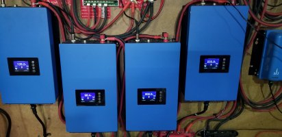
I myself run 4 GTIL2 with 2 paralleled on L1 and 2 paralleled on L2.
L1 GTIL"s share 1 paralleled CT and so do the other 2 GTIL's on L2
In my scenario if the batteries fall below a certain voltage (49V) the 4 GTIL will slowly throttle down to no production and will idle between 3W to 7W each Once Solar starts charging again and the reboot voltage(51V) is reached the 4GTIL will slowly ramp up and start producing again.
In my case no need to shut down AC or DC..
20210609_220933.jpg
Well "standby power" is the real problem in my opinion. My meter says this thing draws somewhere between 75-100 watts on "standby".
Not quite sure why you have that much draw at idle I certainly do not experience that. I have to go all the way back to March to find an evening sleep phase on my GTI's and they were pulling between 0.1A and 0.2A so 24W to 48W.
Wolf
1624633649137.png
 
Last edited:
While I agree with you that switching the inverters AC on and off on a daily basis may not be the best form of power management it technically should not bother the inverter. The anti islanding circuitry is well equipped to handle that.
I myself run 4 GTIL2 with 2 paralleled on L1 and 2 paralleled on L2.
L1 GTIL"s share 1 paralleled CT and so do the other 2 GTIL's on L2
In my scenario if the batteries fall below a certain voltage (49V) the 4 GTIL will slowly throttle down to no production and will idle between 3W to 7W each Once Solar starts charging again and the reboot voltage(51V) is reached the 4GTIL will slowly ramp up and start producing again.
In my case no need to shut down AC or DC..
View attachment 25517

Not quite sure why you have that much draw at idle I certainly do not experience that. I have to go all the way back to March to find a evening sleep phase or my GTI's and they were pulling between 0.1A and 0.2A so 24W to 48W.
Wolf
View attachment 25518
Hi Wolf,
hmmm, well I'm not an expert with these inverters but I can tell you the power draw never drops below something like 75w (or even more like 90w). I'm wondering if it's because you're using limiting mode and I am not. Correct me if I'm wrong, you have PV's connected to charge controler charging your battery, inverter in limiting voltage < 49V standby, reboot at 51V, mode draws from battery not directly from PV's. While I have these vales set, I don't have the checkbox selected because I don't have my battery yet. In other words we maybe talking about different use cases here. User manual was less than clear to me about how these settings worked. Also these are sold under several brand names and I wonder if some work differently than others? The ones I have are 2000w Eco-worthy for whatever that's worth.
 
Correct me if I'm wrong, you have PV's connected to charge controler charging your battery, inverter in limiting voltage < 49V standby, reboot at 51V, mode draws from battery not directly from PV's..............................The ones I have are 2000w Eco-worthy for whatever that's worth.
@john_j_gagne Yes exactly PV > Victron MPPTs > battery > GTIL > mains.
In your case you are running 2 paralleled at 240V correct? And yes the Eco-worthy GTIL look the same.
Considering 0.2 A at 240V for each inverter 48W x2 = 96W seems to make sense now. IDK.
In my case after mid march this year I don't really notice it as my solar so far has kept up with day and night demand including charging the batteries.
I did look at another graph and this one is on the AC side and it shows the GTIL's at idle using around 9W so maybe AC and DC combined is what you are looking at?
Wolf
1624639814462.png
 
Last edited:
@john_j_gagne Yes exactly PV > Victron MPPTs > battery > GTIL > mains.
In your case you are running 2 paralleled at 240V correct? And yes the Eco-worthy GTIL look the same.
Considering 0.2 A at 240V for each inverter 48W x2 = 96W seems to make sense now. IDK.
In my case after mid march this year I don't really notice it as my solar so far has kept up with day and night demand including charging the batteries.
I did look at another graph and this one is on the AC side and it shows the GTIL's at idle using around 9W so maybe AC and DC combined is what you are looking at?
Wolf
View attachment 25520
Well, no. I'm only using one right now and I measured on the ac side. getting .3 - .4 amps @ 240v after the sun goes down.
 
Back
Top