External limiting an GTIL2 SUN-1000G2 with raspberry

Just a side note... I do not think it is good to switch this inverters on the AC side while DC is staying connected. AC is its system power source, while DC is the intermediate power as it could as well come from solar panels.

If you switch AC connection by a timer, you kill the whole unit on daily basis, while there is still energy on the DC side. It might be some unhealthy energy activity going over the components during that shutdown. And then it needs to reboot all the time. I am aware, that that is the inverters "Anti-islanding" feature, but Grid failures typically do not happen twice a day.

If you switch DC instead (contactor + capacitor pre charge resistor), the unit will just change its mode and show the "Starting voltage to low" message. That way is the intended way of usage, but of course, the inverter will continue to draw standby power...
Hie all thanks for you replies. I am happy to report that my inverter is working again. Turns out the problem was not the inverter at all but a faulty contactor that I use on the DC side for switching. Although full voltage was being read, I suppose the mppt circuits were seeing unusual resistances and refuse to operate the inverter. As to switching on the AC side, I have been doing so for 2+ years no problems. I should add that when I switch the inverter off on the AC side the sun is set already (producing no power) and it comes back on just before the sun rises the next morning. I am using a timer.

I am still trying to read the modbus registers on this device so that I can moniter the values using "openhap2". Anyone successfully read the registers and determine there addresses and what they identify. All the data I have found so far is all sketchy. Is this even possible
 
hi folks,
I have created a small ESP32 program (https://github.com/BlackSmith/GFSunInverter), for reading data from an inverter. Benefit of this solution is it can be powered from the inverter (RS232 - pin 9 - 12V). I have ready PR into https://docs.openmqttgateway.com, for sending data to mqtt broker if someone looks for it.
@MartinCZ
This is a neat little ESP package on github for the GTIL.
I may be showing my ignorance here but I am trying to get this to compile on my Arduino IDE.
I am trying to find the ModbusClientRTU.h include but cant seem to find it anywhere. Is this a custom written include?
Thanks for your help
Wolf
 
Hie all thanks for you replies. I am happy to report that my inverter is working again. Turns out the problem was not the inverter at all but a faulty contactor that I use on the DC side for switching. Although full voltage was being read, I suppose the mppt circuits were seeing unusual resistances and refuse to operate the inverter. As to switching on the AC side, I have been doing so for 2+ years no problems. I should add that when I switch the inverter off on the AC side the sun is set already (producing no power) and it comes back on just before the sun rises the next morning. I am using a timer.

I am still trying to read the modbus registers on this device so that I can moniter the values using "openhap2". Anyone successfully read the registers and determine there addresses and what they identify. All the data I have found so far is all sketchy. Is this even possible
Hi Great that you got it working again. How much power does your inverter draw on standby and how much does the timer draw? Just wondering.
 
Hi Roland and Zark: Well "standby power" is the real problem in my opinion. My meter says this thing draws somewhere between 75-100 watts on "standby". Thats the better part of 1kw (conservatively) over a 12 hr period on standby. I've been working on a solar driven (rather than timer) rely which would switch mains off when the sun goes down. So when the dc side is too low to keep the rely energized, mains switch off till the sun comes back. Now I may need a timer to make sure it stays off for at least 30 sec. in the case of heavy clouds (maybe not though too).

Anyway, I'd be interested in seeing a screen cap of the output ZARK is seeing when his inverter boots to "final assembly code". Do you see a flashing cursor on the screen? Maybe code on the screen? I mean who really doubts this thing is embedded linux? If you could get console root access that would be good. Yes?
Well, no. I'm only using one right now and I measured on the ac side. getting .3 - .4 amps @ 240v after the sun goes down.
How are you measuring power?

I have one of these (2KW, 45-90V version), and it draws 3 watts when idle (e.g. no DC input). However, it's idle power factor is 0.03!

If you're just measuring amps and volts and multiplying, I suspect you're going to get a very bogus result.

Another thing to check. If it's drawing 45W (or 90W), it's going to get noticeably warm. Mine isn't detectably warmer then ambient. If you dump ~50W into a device the size of a shoebox without active cooling, it'll rise 20+°C over ambient, even with external heatsink fins.


------

Edit: Looking at my inverter, it's idle current is in fact ~0.5 amps at 240V. However this is a completely reactive load, so there's no actual power consumption in the inverter.
 
Last edited:
How are you measuring power?

I have one of these (2KW, 45-90V version), and it draws 3 watts when idle (e.g. no DC input). However, it's idle power factor is 0.03!

If you're just measuring amps and volts and multiplying, I suspect you're going to get a very bogus result.

Another thing to check. If it's drawing 45W (or 90W), it's going to get noticeably warm. Mine isn't detectably warmer then ambient. If you dump ~50W into a device the size of a shoebox without active cooling, it'll rise 20+°C over ambient, even with external heatsink fins.


------

Edit: Looking at my inverter, it's idle current is in fact ~0.5 amps at 240V. However this is a completely reactive load, so there's no actual power consumption in the inverter.
Hi fake-name:

you said ***If you're just measuring amps and volts and multiplying, I suspect you're going to get a very bogus result.***

Yes that's what I'm doing. My clamp meter reads ~.4 amps @ 240v. How else would one measure the watts?

you said ***I have one of these (2KW, 45-90V version), and it draws 3 watts when idle (e.g. no DC input). However, it's idle power factor is 0.03!***

I'm not sure what "power factor" is or how to measure it or what to do with it when I do. If you can, please explain.

Thank you
 
When using 2 inverters they work together to supply all of the homes load. Both inverters should use the same CTs
I didn't understood your reply but now I do :rolleyes: Are you sure on this ? So when using 2 (same) invertors (2000W each) I should parallel only 1 clamp ? Or serial the invertors on 1 clamp ? Can someone else confirm this also ?
 
I didn't understood your reply but now I do :rolleyes: Are you sure on this ? So when using 2 (same) invertors (2000W each) I should parallel only 1 clamp ? Or serial the invertors on 1 clamp ? Can someone else confirm this also ?
When using a 240v supply from one inverter you need 2 CT clamps. One on each mains. They get wired together to have one output into one inverter. If using 2 inverters you simply splice in another connector so then both inverters use the same 2 CTs
 
@MartinCZ
This is a neat little ESP package on github for the GTIL.
I may be showing my ignorance here but I am trying to get this to compile on my Arduino IDE.
I am trying to find the ModbusClientRTU.h include but cant seem to find it anywhere. Is this a custom written include?
Thanks for your help
Wolf
I use PlatformIO, the required dependencies are specified in platformio.ini. If you need help, write to me by mail rather seclifestor[at]blackserver.cz.
 
When using a 240v supply from one inverter you need 2 CT clamps. One on each mains.
Hello Cheap4Life. Thanks for your reply. I see your comparing to the American system, your speaking about 2 mains to get 240V. This confuses me, as I'm living in Europe ( where a house uses only 1 mains = 2 cables from the provider = 'Neutral' cable and 'Line' cable = 230V). So my 2 pieces GTIL 2000W are paralleled on the single one mains ( we call it a 'fase') I have, to be able to compensate up to 4000 W net use. Should they both still use the same single one clamp ?
 
Yes that's what I'm doing. My clamp meter reads ~.4 amps @ 240v. How else would one measure the watts?

With a wattmeter.

I'm not sure what "power factor" is or how to measure it or what to do with it when I do. If you can, please explain.


Effectively, power factor describes the phase relationship between the AC voltage and the current. If your current is 0° offset from the voltage, you have a pure resistive load, and current * voltage = power. If your current is +90° or -90° from the voltage, you have no real power consumption even if your load is drawing infinite amps. For these inverters, I suspect there is a fairly large amount of capacitance across the output creating a highly reactive load.

For AC systems, voltage * current just gives you VA (or volt-amps), or apparent power.

Your normal house power meter measures real power, not apparent power, as do wattmeters.

Basically, they integrate the instantaneous voltage * instantaneous current, either mechanically or electronically.
 
Last edited:
Hello Cheap4Life. Thanks for your reply. I see your comparing to the American system, your speaking about 2 mains to get 240V. This confuses me, as I'm living in Europe ( where a house uses only 1 mains = 2 cables from the provider = 'Neutral' cable and 'Line' cable = 230V). So my 2 pieces GTIL 2000W are paralleled on the single one mains ( we call it a 'fase') I have, to be able to compensate up to 4000 W net use. Should they both still use the same single one clamp ?
Yes, you would use one clamp for single phase. All inverters using one clamp
 
I use PlatformIO, the required dependencies are specified in platformio.ini. If you need help, write to me by mail rather seclifestor[at]blackserver.cz.
Ah yes @MartinCZ my ignorance shines again. I have downloaded VS and installed Platform IO I will muddle around with this for a while and see if I can get this to work. How hard can it be?:unsure:.
Thanks for the pointers and I will be in touch.
Wolf
 
Edit: Looking at my inverter, it's idle current is in fact ~0.5 amps at 240V. However this is a completely reactive load, so there's no actual power consumption in the inverter.
So it draws ~.5 amps @ 240v but is not consuming 120w (because it's a completely reactive load)? I have no idea what a completely reactive load is as apposed to any other "type" of load. I'm not sure I knew there were "types" of loads. The question remains, then how do we measure the idle load given your assertions of reactive load.

I am an amateur. I have no intention to troll, instigate, or antagonize. If you will, please allow me the benefit of the most generous reading of the above.

Thank you

edit*** just saw you message above after I posted this. I think I understand what you're saying. I just got a PZEM-016. Once I get it installed we'll see what it reports.

Thanks for your help
 
Last edited:
So it draws ~.5 amps @ 240v but is not consuming 120w (because it's a completely reactive load)? I have no idea what a completely reactive load is as apposed to any other "type" of load. I'm not sure I knew there were "types" of loads. The question remains, then how do we measure the idle load given your assertions of reactive load.

I am an amateur. I have no intention to troll, instigate, or antagonize. If you will, please allow me the benefit of the most generous reading of the above.

Thank you

edit*** just saw you message above after I posted this. I think I understand what you're saying. I just got a PZEM-016. Once I get it installed we'll see what it reports.

Thanks for your help
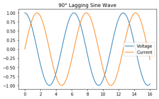
1626337594328.png

So, in the image, the current lags the voltage by 90°. This is a completely inductive load. If we calculate the power (V * A for each time increment):

1626337818716.png

The power is therefore a resulting sine centered at 0W. The average of this sine is therefore 0 watts, so there's no actual dissipation in the device, despite all the current flowing. Note that you will still get losses in the wiring, as you still have the current flowing, it's just basically fed back into the mains continuously.

The same is true for a capacitive load. It just leads to the current leading the voltage by 90°, instead of lagging.

1626338297072.png

If we take a device with 0° phase offset between the current and voltage:

1626338032334.png

You can see the power never goes negative, so you have "true" power dissipation.

Power factor is effectively just a ratio between the real power (e.g. average of the instantaneous product of the voltage + amperage), and the average voltage * the average current.

For the above, both examples with 90° offsets have a power factor of 0, while the 0° offset has a power factor of 1.
 
View attachment 25629

So, in the image, the current lags the voltage by 90°. This is a completely inductive load. If we calculate the power (V * A for each time increment):

View attachment 25631

The power is therefore a resulting sine centered at 0W. The average of this sine is therefore 0 watts, so there's no actual dissipation in the device, despite all the current flowing. Note that you will still get losses in the wiring, as you still have the current flowing, it's just basically fed back into the mains continuously.

The same is true for a capacitive load. It just leads to the current leading the voltage by 90°, instead of lagging.

View attachment 25633

If we take a device with 0° phase offset between the current and voltage:

View attachment 25632

You can see the power never goes negative, so you have "true" power dissipation.

Power factor is effectively just a ratio between the real power (e.g. average of the instantaneous product of the voltage + amperage), and the average voltage * the average current.

For the above, both examples with 90° offsets have a power factor of 0, while the 0° offset has a power factor of 1.
Thanks for taking the time. After your other message I found this:


All this help me understand that watts can't really be measured with a multimeter (something I did not know) because the measure of current and volts must be taken simultaneously in order to determine the power factor as you said.

amps * volts * power factor = watts

Anyway I got my watts meter installed and running (PZEM-016 from Amazon). The readings show that the GTIL2000 watt inverter draws about 1.4 watts in standby. This is great news because it makes everything much simpler. I had ordered a two pole relay I was going to control with a small solar panel to switch the power. Now this is not necessary because the standby power use is so small.

Here are the readings from the PZEM-016 from last night at 8:00 PM:

date time volts amps watts Hz PF whrs
2021-07-14 20:00:45.131831 240.4 0.504 1.4 60.0 0.01 10579

They're nice little units and very cheep. Running on a Raspberry PI zero w makes for a nice system.
 
Hello friends,

I'm new here but I would like to take a look at my project with the IAMMETER WEM3080T as a current measuring device, 3x Sun 1000 that are controlled by an Arduino with a digital analog converter. It works really well in this configuration.

There are many good approaches and therefore I would like to introduce myself to the project, maybe it will help one or the other further in the project.

Here is the link to the projects where mine is included: https://imeter.club/topic/58
 
Hi,
I recently joined this group, I started with my introduction here. This is where we left off:
Best as I can make out the internal voltage reference is off by 1.4 volts at the panel sense. It says that my panel voltage is 47.5 when it is actually 49.9 volts. So I'm guessing that the firmware has a lower limit of 47.5 volts that it will take the panels to at maximum output. But because the panels are floating at almost 50 volts, it is just not getting the current they are capable of.

From there Cheap-for-life tells me my panel voltage is too low for the 45-90v version. So, I miss understood what I was buying and the 22-65v will handle a Voc that could hit > 65v, is ok. The panels are installed on the roof, there is no changing them They are pairs of 24v, wired 48v.
 
Hi,
I recently joined this group, I started with my introduction here. This is where we left off:


From there Cheap-for-life tells me my panel voltage is too low for the 45-90v version. So, I miss understood what I was buying and the 22-65v will handle a Voc that could hit > 65v, is ok. The panels are installed on the roof, there is no changing them They are pairs of 24v, wired 48v.
You might want to start a new post in the inverters section. This is for external limiting a GTIL2. I got an a** chewing on this post before for going off topic.
If your panel will be right at 65voc then you have a high chance of overvolting the 22-65v inverter. What is the voc of one of your panels?
 
Back
Top