External limiting an GTIL2 SUN-1000G2 with raspberry

It's a while since I dabbled with this, but here is some info and images I created at the time if it helps:

The interface is RS232:


View attachment 2566


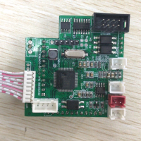
The essential functions of the interface board:

View attachment 10160


The 8 pins on the left represent the ribbon cable from the main board. The 9 pins on the right represent the RS232 D connector. The centre pins are the connections to the RS232 level shifter IC (charge pump etc components not shown for clarity).
I'm not sure what the connection to pin 9 on the D connector is, but I suspect it is to provide power to a wifi type dongle, so watch out for that if what you connect to it is not expecting that as that is not standard on an RS232 connector.

Some screen shots of settings I used in a modbus application:


View attachment 3646
Hi! Thanks for this interesting thread!
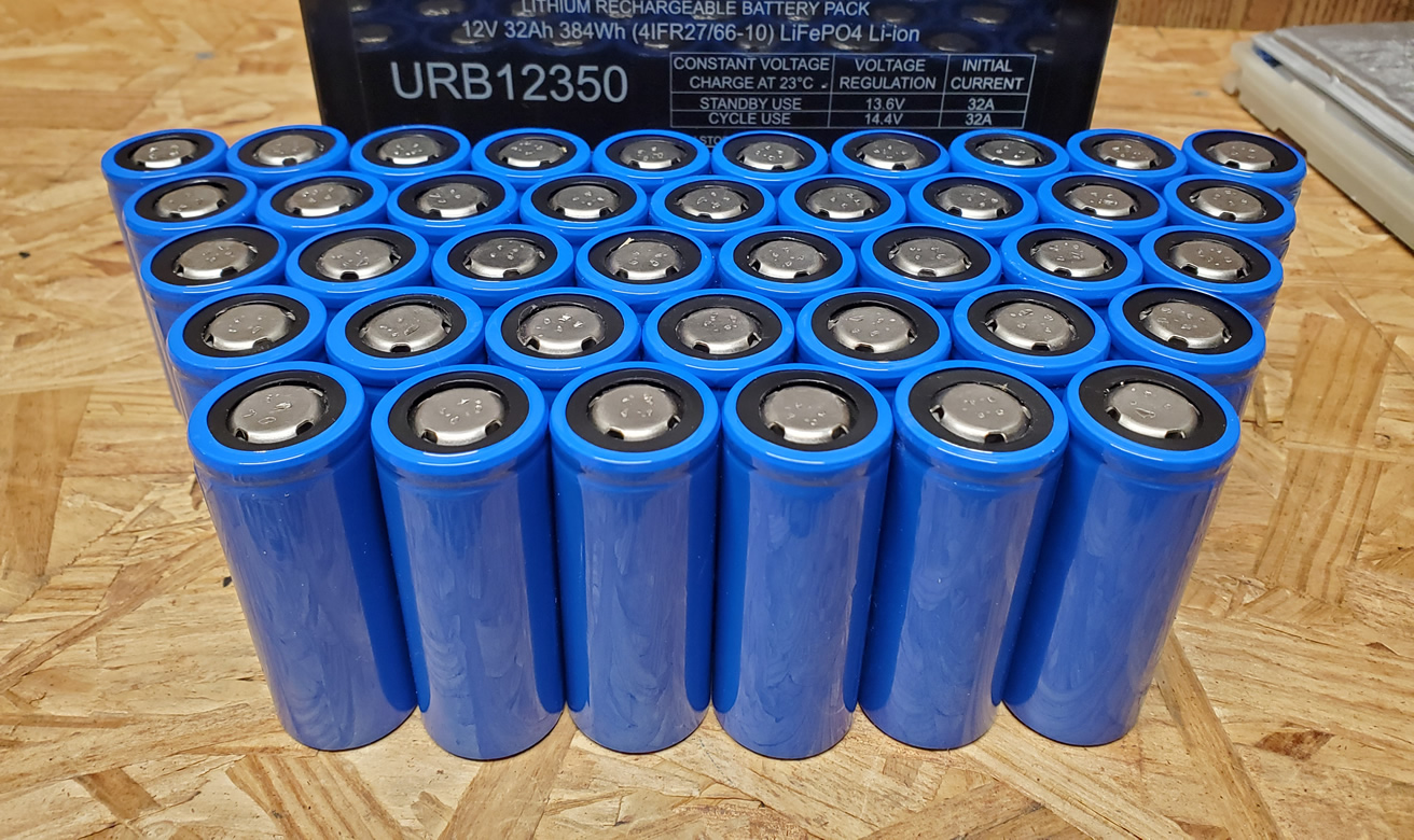
I have a SUN-1000GTIL2 the 22-65v version for Europe with FW 6.1.
I've checked your diagram and the Max3232 datasheet pin-out, all is correct.
I cannot get any responses from my inverter with the Modlink, always returns "FAIL: Response timeout expired".
I've tried 6 different USB to serial adapters (rs232 and rs485).
I'm out of DB9 female connectors to make a cable to sniff the port so any tips on getting it running would be REALLY appreciated!
Maybe the 6.1 uses a different baud rate?

Cheers!
 
Okay, made a 4th cable, and another RS232 to USB adapter. Restarted the unit and it worked. Must have been the unit getting bogus stuff on the Serial port...
I'm really looking for a way to read when the limiter is enabled so I can charge batteries with excess energy.
I can only get data from a few registers;
registerdecimalhexadecimaldescription
0​
2​
0002Device Type
2​
1​
256​
0100mailing address
2​
1​
0001Communication protocol version
1​
3​
12849​
3231SN 1,221
4​
12344​
3038SN 3,408
5​
12338​
3032SN 5,602
6​
13364​
3434SN 7,844
7​
14137​
3739SN 9,1079
43​
12336​
3030Power on/off enable
59​
512​
0200Running state
60​
10​
000AActive power generation on the day
1​
kWh
63​
106​
006ATotal active power generation low word
10.6​
kWh
70​
2218​
08AAGrid voltage AB
221.8​
V
86​
150​
0096Output active power low word
15​
W
109​
250​
00FADC voltage
25​
V
 
I've read some things on German forums, but all are just about the 1000W GTIL2.
This one you can control with a small change to its controller PCB and then you just need external 0 to 5V and a resistor voltage divider.
That is the solution I'd like for the 2000W GTIL2, but it seems it only works with the 1000W version :(

For me this means right now: I have to buy the 1200W Soyo inverter and control it via RS485 :/
Hi NikA,

Could you please send a link with details of this 1200W Soyo inverter?

Many thanks.
 
 
Hi NikA,

Could you please send a link with details of this 1200W Soyo inverter?

Many thanks.
Sorry, I see this just now.

here it is:

beware! it has no LCD (I thought it had, even the manual and sheets that come with it show an LCD and buttons ...)
 
ok, I tried some things myself just now.

Applying an external voltage doesn't do anything with my GTIL2.
I did hope to control it using an DAC as you do it with DCDC converter feedback resistors etc.

Then I tried limiting using a fix 1k resistor, that dropped the power from 450 to 340W.
But the current! 300mA through 1k, that explains why digital Rpot die, it's way too much for them.

I suppose nobody did examine the controller PCB any further?
I can not get the PCB out right now, but it would be interesting to see where the 2pin connector is connected to, I could not beep it with my multimeter today, not enough time to do so :/
i tried the connector for the 10k potentiometer (at bottom/right on the picture) - the voltage here was 3.3V, and the current at 0 Ohm 330uA so the internal resistor was also 10 kOhm - with my pcb circuit (20x50mm) I now can control the complete power range of (two) SUN1000-GTIL2 using 0 - 3.3V as input which controls the MosFET which is simulating the potentiometer ....
pcb circuit based on : https://secondlifestorage.com/index...il2-sun-1000g2-with-raspberry.2328/post-63741
:)
 

Attachments

  • mainboard.png
    mainboard.png
    603.7 KB · Views: 128
  • IMG_5778.JPG
    IMG_5778.JPG
    69.6 KB · Views: 125
Last edited:
ah, here you wrote it :)

very odd though, maybe that's the difference between 1kW and 2kW version?
My amperemeter did show a much higher current @ 1kOhm as you saw in my post above :eek:

I think I'll try this circuit too, I already have something similar around, just different parts and I need to add the FET part after the opAmp ... I'll report about it as soon as I've got something wired up.

Applying the voltage directly did not work, now I'm curious because with the FET it should work :eek:
 
Sorry, I see this just now.

here it is:

beware! it has no LCD (I thought it had, even the manual and sheets that come with it show an LCD and buttons ...)
Hi NikA,

Just saw your reply.
Thanks for sharing. Do you know how you can change the output power on these inverters? Via communication? Wifi? RS485?

Thanks
 
Hello friend I have found this data
 

Attachments

  • IMG_20221031_121453.jpg
    IMG_20221031_121453.jpg
    528.6 KB · Views: 61
Hello,

Thanks for all the interesting stuff you figured out!

I have a SUN 2000 and testet the Modbus communication over the RS232 port using the windows tool QModBus. I am able to read the registers as shown in OiD's table. For example the values for Grid Voltage (Register 70) and DC Voltage (Register 109) make sense, but when I read Register 86 (Output active power) I get random values. I get 0 when the power is 0, but all other make no sense:

Power / read values:
0W / 0
50W / 168, 270 ...
100W / 366, 474, 582 ...
200W / 750, 1050 ...
300W / 1308, 1758
400W / 2088, 2622, 3018
500W / 3330, 3732 ...

What's going on there? Is this a speciality of the SUN 2000 inverter or is my device defective?

Thanks a lot!
 
Ok, it seems there is an extreme low pass behaviour. When I wait a few (!) minutes while the power is constant, I get realistic values.

I wonder why the values at the RS232 port are not the same as shown on the LCD and why the actualisation rate is that low...

It seems the inverter circuit works standalone and the LCD and RS232 port also. They are not synchronized, every circuit calculates its own values independently 🤷‍♂️
I have that same behavior with my Deye SUN-5K-SG03LP1-EU. For example, voltage is set to 230V AC on the display, all multimeters measure 230V AC, yet the display tells me the current voltage is 234 to 235V AC. Same for the values it spits out over the wifi stick / rs232 port.
 
Hello,

Thanks for all the interesting stuff you figured out!

I have a SUN 2000 and testet the Modbus communication over the RS232 port using the windows tool QModBus. I am able to read the registers as shown in OiD's table. For example the values for Grid Voltage (Register 70) and DC Voltage (Register 109) make sense, but when I read Register 86 (Output active power) I get random values. I get 0 when the power is 0, but all other make no sense:

Power / read values:
0W / 0
50W / 168, 270 ...
100W / 366, 474, 582 ...
200W / 750, 1050 ...
300W / 1308, 1758
400W / 2088, 2622, 3018
500W / 3330, 3732 ...

What's going on there? Is this a speciality of the SUN 2000 inverter or is my device defective?

Thanks a lot!
Grid Home W values
not available to rs232

Only by LCD display
 
Good news for Modbus RS485

Today i did phone with the developer in China and he will help us...

After Phone he did write me this:

"OK, I known. The protocol is written by me.
Because my poor english, I will ask someone to translate the protocol."

For culture understanding: Its very unusual that in china say something like this. He did excuse indirect not to make a translation. So guys let be fair... i gues the make us a cheap price for ther Wifi products and as far i see we should work hand in hand... Their main business are not this kind of dongles but to make a dongle yourself with esp8266 is not much more cheaper if you set the cost of a case in comparison so i think to honor a bit their work we can go there at a later point and buy directely there. And i guess as long we are here in developement the price as far i did understand is 25 $ more cheap than the official prices i saw in facebook... so it can be a win win situation for both sides...
Hello do You have detail and news i have make code for esp8266 for read by uart data lcd but have problem in the day.
View: https://youtu.be/DfuTloXaQu8

View: https://youtu.be/mLScB_W9C2k

View: https://youtu.be/Nai7H2lYTTY


Thank s cent0
Github
 
Hi - i dont know if this Thread is still for Interest.

But there is a way to flash a alternative Firmeware on this Device so you can do Limiting by using RS232/Modbus RTU.

Everything you want to know is to find on https://www.der-kanal-homepage.de/ (German) - but you need a Pic programmer and the Firware.
With this Firmware you can use a RS232/RTU <> Ethernet Modbus Device Converter to Monitor and control your Sun2000 out of any Network System you want ...

Best Regards
 
Back
Top