Final criticism before the build

pipedream

New member
Joined
Apr 22, 2021
Messages
6
Hi everyone

Been slowly getting ontop of my DIY power wall project which has now morphed into a portable pack that I intend to mount to a trolley.
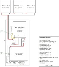
I have mocked up the design and wiring etc and was hoping to get any final feedback and comments to confirm I have everything sized and wired correctly.

Any criticism is greatly appreciated and please let me know if I have missed any details on the build.

Cheers
 

Attachments

  • Powerwall Design.jpg
    Powerwall Design.jpg
    181.6 KB · Views: 134
Yes, the outline looks straight-forward / good.

One thing I noticed is the 100a between battery and MPP Solar. I have a 3000w MPP Solar 3048 and I've run right up to the 3000w a few time and 3000w/26v = 115a. Suggest a 125a circuit breaker instead of 100a so you can use all 3000w (assuming the wire can handle 125a). The MPP Solar will take care of itself (auto shut-off) if you go over 3000w :)
 
Last edited:
Looks perfect to me! Yes, I thought the same thing as OGITC about the 100A breaker LOL

Very good, congrats man! :D
 
Last edited:
Couple thoughts and things you probably want to double check.

It was actually hard to find but double check the DC solar voltage range for the MPPT I found a range of up to 80vdc or 145vdc depending on if you believe the webpage or the PDF here https://www.enfsolar.com/pv/inverter-datasheet/11199 which would mean you want to put all the panels in parallel not series. I wouldn't even put two in series since that is really close to the limit and you don't want to make the mistake I did and forget to calculate the cold temperature coefficient which causes the panels to exceed the max OC voltage when very cold. Also note the MPPT rang which is probably what you want to use as an actual usable voltage range since charging will probably stop above that level it just won't fry things until the higher max value. As an example I have a system I sized with 3 series 44voc on a 150v max mppt and when it is cold like right now the charging stops because the voltage exceeds 140v.

Also your solar DC breaker is probably a bit big for if they are in series(which is how it is currently drawn) but pretty close if they are all parallel.

I also agree that a 125A continues duty breaker would be a better fit as long as you are using that 2awg cable not the 4awg for that leg.

It looks like your BMS is probably a Daly type one in which case you want to oversize it a lot so the mosfets don't burn up under a potential 100A+continues load. Also if this is going to be a smart BMS you probably don't need a separate battery monitor.

Last thing is you will likely have to tweak/hack the charging parameters to fit Lion since the Mppt manual reads that it is only programed for Lead Acid. I have found usually just setting the absorption time to 0 and appropriate bulk & float levels works well with an mppt.

Have fun :)
 
Hi everyone, thank you very much for your advice.
I have now ordered a 125 amp breaker and will double check the configuration of the solar panels.

As this system is only going to have a smallish load to run some pumps, lights and air stones etc for an aquaponics setup, I don't suspect I will need all 3 panels for charging. I am looking at mounting two panels together with hinges and stands to make the whole thing portable, but thats once everything else has been done.
Cheers guys 🍻
 
Back
Top