
rebelrider.mike
Member
- Joined
- May 25, 2017
- Messages
- 614
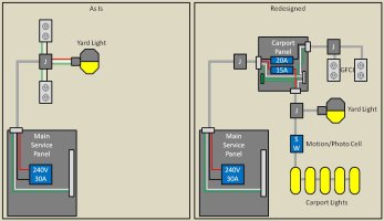
Springtime in the Pacific Northwest has pulled my attention back to an outdoor circuit I've never been happy with. When I first moved into my house, there was a cable going to the carport that kind of went nowhere. I fixed it up as a multibranch circuit, that is two circuits sharing a common neutral. One branch feeds a yard light, and the other feeds a couple receptacles.
The cable is a UL listed UF with sunlight resistance, and it is a 10/3 AWG with ground.

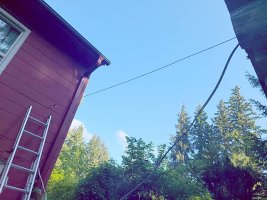
I'm pretty sure it's a good cable to keep using, but I'm not excited about the way it's mounted to the side of the house.
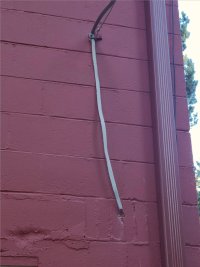
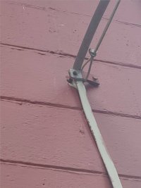
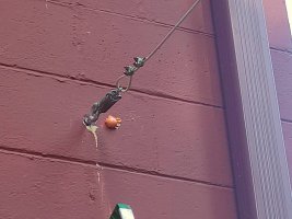
It's just a bit of metal bolted to the cinder block. There is a supporting non-conducting cable that I imagine is supposed to be supporting the power cable, but at no point are they actually attached to each other. On the carport end, the support cable has some kind of shock absorber spring that hooks to nothing.
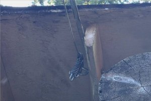
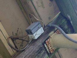
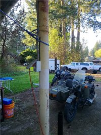
I'm pretty sure the height is ok. I measured once, and I think it's just high enough to be allowed by the US NEC. Once under the carport, the UF cable ends in a junction box, and is separated into the two branches.
So here are the things that bug me about the circuit:
The cable is a UL listed UF with sunlight resistance, and it is a 10/3 AWG with ground.
I'm pretty sure it's a good cable to keep using, but I'm not excited about the way it's mounted to the side of the house.
It's just a bit of metal bolted to the cinder block. There is a supporting non-conducting cable that I imagine is supposed to be supporting the power cable, but at no point are they actually attached to each other. On the carport end, the support cable has some kind of shock absorber spring that hooks to nothing.
I'm pretty sure the height is ok. I measured once, and I think it's just high enough to be allowed by the US NEC. Once under the carport, the UF cable ends in a junction box, and is separated into the two branches.
So here are the things that bug me about the circuit:
- It's fed by a 2-pole 30A breaker. Fine for the gauge of wire, but too high for what it's being used for.
- I think the support wire should be attached by a separate mechanism than what attaches the power cable to the house.
- I don't like how the cable itself is attached to the house.
- Nor do I like that rather tight 90 degree turn it's making. Though I'm not keen to try to unbend in now that it's done.
- The receptacles are not GFCI protected.
- I want to add more lights so the underneath of the carport is lit.
- Install an outdoor load panel and two breakers. A 15A for the lights, and a 20A for the receptacles.
- Install an eyebolt through the cinder block to attach the support cable to the house. And add zip ties or something so the support cable actually does some supporting.
- I'm not sure how the cable should be attached to the house. I've not figured this one out yet.
- Not sure what to do with that tight 90 degree angle either. Bend a copper wire too many times and it will snap.
- Easy enough to replace the receptacles with GFCI ones.
- Adding lights (and a motion sensor) under the carport should be easy. The yard light uses 0.4A, and new smaller lights will add something like another 0.4A. So 15A will be more than enough.