Araknid
Member
- Joined
- Jun 1, 2020
- Messages
- 54
1) Project Goal
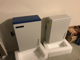
Power wall built with Sony 20Q/25R,Samsung VTC5(a) and some VTC6 cells harvested from drill battery packs. built into a high voltage stack to power a Solax Hybrid X3-8.0T inverter for a peak powerof 10kW
2) Current Phase:
Battery Capacity + IR/SoCTesting
3) ProjectSpecification:
Voltage: 180-240v[size=small](min)/360-470v(max)[/size]
Current: 25A (30A peak, 60s, fused 50A)
Capacity: 30kWh
Power: 3-5kW[size=small][size=small][size=small](min)[/size][size=small][/size][size=small]/[/size][/size]7-10kW(max)[/size]
Configuration: 12s40p5s(min) /12s40p10s (max)
Battery Management: foxBMS (foxBMS.org; Open Source BMS); PCB re-work to optimise IO
Inverter: Solax Hybrid X3-8.0T
Batteries:[size=small]INR18650-25R,[size=small]INR18650-20Q,[size=small]US18650VTC6,[size=small]US18650VTC5/5a,[size=small]US18650VTC3[/size][/size][/size][/size][/size]
Source:Powertool battery packs. Single source, stable supply and quality
4) SubProject:
4.1) Battery Capacity Tester
Arduino ATMEGA2560 with fixed resistor load (~1.8 to 1.4A)
https://github.com/HSBNE/atmega-18650-discharger/
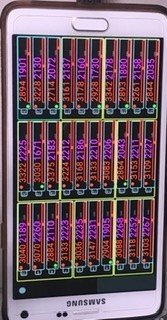
Phase 1: functional updates complete. Calibrated sockets, time accurate and functional data logging system with barcode scanning for tracking individual cells and their test data. Documenting the phase 1 project before building phase 2.
Phase 2: will be a new online IR measurements over SoC to log both voltage, current, temp, IR over the effective 3.9 to 3.0 OCV "nominal" capacity range
4.2) Battery Charger
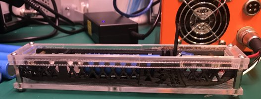
30-bay TP4056 + PC power supply in laser cut perspex frame. Simple, effective.
Phase 2:Build new 30-bay unit based on Tp5100. Buck converter for improved energy efficiency from the 12V ATX PSU Rail and faster charge times using 2A over ~0.5-1A (depending on how the wind blows... Tp4056)
4.3)Battery Management System
foxBMS based (foxBMS.org) Master/Slave BMS based on LTC6811
Optimized IO and component substitution
https://github.com/ArakniD/foxbms

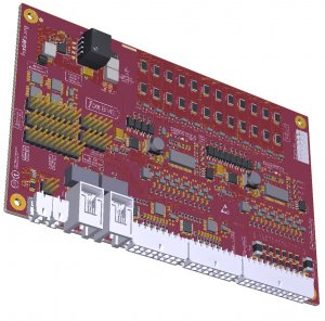
PCB with reduced IO as the source project supports far more configuration options than I need. Substituted some parts too. I promise to detail what i've substituted and any new features added..
4.4) picoReflow raspberyPi based PCB Oven
https://github.com/HSBNE/picoReflow
I needed a PCB over for this and other projects...
5) Research and Development:
5.1) 4-wire 18650 holder
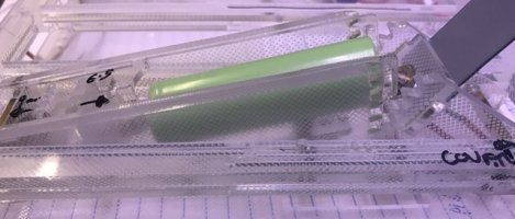
Pivot and self-latching to enable testing of naked cells, safely. And enables IR measurements over SoC. IR is not a static measurement, and it depends on temperature, SoC, time since rest. Many factors. I have seen the effects of high IR at end of SoC through a number of discharge cycles on otherwise 'OK' cells. I would prefer to bin these than include them in my packs.
concept drawing.. Initial thoughts..

5.2) Lithium Battery cell off-gassing detection and fire Prevention
ccs6811 based chip to detect gasses from a potential lithium fire.. more details later
6) Reference Material:
6.1) Analysis of the Effect of the Variable Charging Current Control Method on Cycle Life of Li-ion Batteries
6.2)Timescale and SoC affects on IR measurement
6.3)On-line Electrochemical Impedance Spectroscopy for Lithium-Ion Battery Systems
6.4) foxBMS.org : OpenSource Battery Management System
6.5)A Comprehensive Approach for the Clustering of Similar-Performance Cells for the Design of a Lithium-Ion Battery Module for Electric Vehicles
Power wall built with Sony 20Q/25R,Samsung VTC5(a) and some VTC6 cells harvested from drill battery packs. built into a high voltage stack to power a Solax Hybrid X3-8.0T inverter for a peak powerof 10kW
2) Current Phase:
Battery Capacity + IR/SoCTesting
3) ProjectSpecification:
Voltage: 180-240v[size=small](min)/360-470v(max)[/size]
Current: 25A (30A peak, 60s, fused 50A)
Capacity: 30kWh
Power: 3-5kW[size=small][size=small][size=small](min)[/size][size=small][/size][size=small]/[/size][/size]7-10kW(max)[/size]
Configuration: 12s40p5s(min) /12s40p10s (max)
Battery Management: foxBMS (foxBMS.org; Open Source BMS); PCB re-work to optimise IO
Inverter: Solax Hybrid X3-8.0T
Batteries:[size=small]INR18650-25R,[size=small]INR18650-20Q,[size=small]US18650VTC6,[size=small]US18650VTC5/5a,[size=small]US18650VTC3[/size][/size][/size][/size][/size]
Source:Powertool battery packs. Single source, stable supply and quality
4) SubProject:
4.1) Battery Capacity Tester
Arduino ATMEGA2560 with fixed resistor load (~1.8 to 1.4A)
https://github.com/HSBNE/atmega-18650-discharger/
Phase 1: functional updates complete. Calibrated sockets, time accurate and functional data logging system with barcode scanning for tracking individual cells and their test data. Documenting the phase 1 project before building phase 2.
Phase 2: will be a new online IR measurements over SoC to log both voltage, current, temp, IR over the effective 3.9 to 3.0 OCV "nominal" capacity range
4.2) Battery Charger
30-bay TP4056 + PC power supply in laser cut perspex frame. Simple, effective.
Phase 2:Build new 30-bay unit based on Tp5100. Buck converter for improved energy efficiency from the 12V ATX PSU Rail and faster charge times using 2A over ~0.5-1A (depending on how the wind blows... Tp4056)
4.3)Battery Management System
foxBMS based (foxBMS.org) Master/Slave BMS based on LTC6811
Optimized IO and component substitution
https://github.com/ArakniD/foxbms


PCB with reduced IO as the source project supports far more configuration options than I need. Substituted some parts too. I promise to detail what i've substituted and any new features added..
4.4) picoReflow raspberyPi based PCB Oven
https://github.com/HSBNE/picoReflow
I needed a PCB over for this and other projects...
5) Research and Development:
5.1) 4-wire 18650 holder
Pivot and self-latching to enable testing of naked cells, safely. And enables IR measurements over SoC. IR is not a static measurement, and it depends on temperature, SoC, time since rest. Many factors. I have seen the effects of high IR at end of SoC through a number of discharge cycles on otherwise 'OK' cells. I would prefer to bin these than include them in my packs.
concept drawing.. Initial thoughts..

5.2) Lithium Battery cell off-gassing detection and fire Prevention
ccs6811 based chip to detect gasses from a potential lithium fire.. more details later
6) Reference Material:
6.1) Analysis of the Effect of the Variable Charging Current Control Method on Cycle Life of Li-ion Batteries
6.2)Timescale and SoC affects on IR measurement
6.3)On-line Electrochemical Impedance Spectroscopy for Lithium-Ion Battery Systems
6.4) foxBMS.org : OpenSource Battery Management System
6.5)A Comprehensive Approach for the Clustering of Similar-Performance Cells for the Design of a Lithium-Ion Battery Module for Electric Vehicles


