High voltage hybrid inverter (GW6000-EH) with EV battery (Chevy Volt)

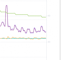
I'm planning to investigate this problem, but this will require some changes in my setup. I will connect the Rasp Pi to the inverter's MODBUS port and log the data in real-time. Yesterday, after a full restart of the inverter, there is an improvement in its work:
night_dis1.png
This is a four-hour segment during the evening, and the grid consumption is zero. But during the day, the situation is like before. Anyway, this will need more attention.
I've checked a self-consumption from the battery in the off-grid mode, without any loads. At 360V, there are peaks of 130mA readings at multimeter, which give around a 45W peak. The average is lower, but I will need a more complicated setup to measure exactly.
 
I'm planning to investigate this problem, but this will require some changes in my setup. I will connect the Rasp Pi to the inverter's MODBUS port and log the data in real-time. Yesterday, after a full restart of the inverter, there is an improvement in its work:
View attachment 24353
This is a four-hour segment during the evening, and the grid consumption is zero. But during the day, the situation is like before. Anyway, this will need more attention.
I've checked a self-consumption from the battery in the off-grid mode, without any loads. At 360V, there are peaks of 130mA readings at multimeter, which give around a 45W peak. The average is lower, but I will need a more complicated setup to measure exactly.

Thanks for this offgrid self- consumptions, very interesting. I guess 45W is an upper bound...
I don't know if you have a domotic OS such Home assistant, but I know there is a way to collect data from LAN : https://github.com/mletenay/home-assistant-goodwe-inverter
 
Last edited:
Thanks for the link. The Home assistant is on my to-do list :)

Now about two improvements I've made to my system during last weeks. The first one is water cooling of the batteries. I'm using the original cooling ports of the modules and just added a tiny pump and pipes. The pump is brushless, consumes around 6W at 12V, and gives a good water flow. I have no heat problems from modules but decided to add this cooling system for additional protection against unexpected failures (e.g., thermal runaway). Of course, adding a liquid coolant to the systems brings other problems. I've to change the coolant twice before found one with lower conductivity. Now I'm using a mixture of deionized water and propylene glycol with conductivity around five uS/cm. (For example, my tap water is around 100 uS/cm). A picture of the system:

water_cooling.jpg

The second one: I've just ported the current code of BMS communication software to embedded MCU (STM32F446). I'm using one controller that I made some time ago. Although it's not optimal for the current application, it has two CAN port needed for BMS software and 12V power input. I've only added an external CAN transceiver for the second port.

mcu1.jpg
The connections are a little bit messy, and I have to rewire them. But the controller is working and successfully translates messages from the battery to the inverter. Pors of the current solutions:
  • higher reliability
  • lower power consumption: 1W against 6W for the Rasp Pi
  • It has needed hardware to support a battery current measurement with ext. sensor
  • It can control an external relay for battery protections
Cons:
  • It will make coding and debugging a little bit harder.
  • I will need an additional uplink port for battery monitoring.
 
Cool that you made the cooling work again. As you probably know it’s completely unnecessary unless you are pulling a crazy amount of amps from them. Mine never even get warm pulling 70amps from them at 60v. You mentioned thermal runaway. I’m thinking the little bit of cooling won’t help much against that.
 
Last edited:
Thanks for the link. The Home assistant is on my to-do list :)

Now about two improvements I've made to my system during last weeks. The first one is water cooling of the batteries. I'm using the original cooling ports of the modules and just added a tiny pump and pipes. The pump is brushless, consumes around 6W at 12V, and gives a good water flow. I have no heat problems from modules but decided to add this cooling system for additional protection against unexpected failures (e.g., thermal runaway). Of course, adding a liquid coolant to the systems brings other problems. I've to change the coolant twice before found one with lower conductivity. Now I'm using a mixture of deionized water and propylene glycol with conductivity around five uS/cm. (For example, my tap water is around 100 uS/cm). A picture of the system:

View attachment 24356

The second one: I've just ported the current code of BMS communication software to embedded MCU (STM32F446). I'm using one controller that I made some time ago. Although it's not optimal for the current application, it has two CAN port needed for BMS software and 12V power input. I've only added an external CAN transceiver for the second port.

View attachment 24357
The connections are a little bit messy, and I have to rewire them. But the controller is working and successfully translates messages from the battery to the inverter. Pors of the current solutions:
  • higher reliability
  • lower power consumption: 1W against 6W for the Rasp Pi
  • It has needed hardware to support a battery current measurement with ext. sensor
  • It can control an external relay for battery protections
Cons:
  • It will make coding and debugging a little bit harder.
  • I will need an additional uplink port for battery monitoring.

That's a pretty good news :). Why not a basic ESP32 ? as MCU ? You need 2 CAN for the dialog ?
 
@Cheap 4-life, I agree with you. The batteries working as ESS doesn't need extra cooling. My peak currents are even lower, around 10-15A. But after reading about this incident involving a battery fire, I've decided to take whatever measures possible. The water in the system is an additional thermal buffer, which will absorb and dissipate the heat in cell failure. Another advantage of the Chevy Volt battery design is the physical separation of the individual cells. Anyway, I hope that I will never test this in a real-life scenario.

@SeByDocKy, I'm not familiar with ESP32, and I need two CAN port for BMS communication because the speeds are different. The inverter uses 250kbps, but the battery talks at 125kbps.
 
Last edited:
@Cheap 4-life, I agree with you. The batteries working as ESS doesn't need extra cooling. My peak currents are even lower, around 10-15A. But after reading about this incident involving a battery fire, I've decided to take whatever measures possible. The water in the system is an additional thermal buffer, which will absorb and dissipate the heat in cell failure. Another advantage of the Chevy Volt battery design is the physical separation of the individual cells. Anyway, I hope that I will never test this in a real-life scenario.

@SeByDocKy, I'm not familiar with ESP32, and I need two CAN port for BMS communication because the speeds are different. The inverter uses 250kbps, but the battery talks at 125kbps.
AFAIK, the ESP32 got 3 CAN.... so it's not a big deal to handle your configuration. In my futur case, if I'll go for a LifePO4 prismatic batteries, I guess only 1 CAN will be required.
 
@yasko some news about the DIY communication with the GoodWe ? and about the grid extra consumation ? Do you have a direct contact with Goodwe, coz they are nerver answering to any question.....
 
@SeByDocKy, there is some new info, and I will share it in the next posts, but now in brief:
  • I've made a new setup with Rasp Pi and now communicating with the inverter via MODBUS RTU protocol at 9600bps. The protocol description is not publicly available, but I've found helpful info from the OpenEMS project.
  • Now I'm collecting data regarding extra grid consumption and can confirm that it happens when the inverter charges the battery, and it's in the range of 100-200W. I've still not contacted Goodwe because I need to figure out what exactly happens.
  • During the MODBUS tests this weekend, I've found a minor issue in the BMS CAN communication protocol that I'm using. I now fixed it and will update the docs.
  • I've rechecked battery consumption in off-grid mode using some fancy hardware (AMC3302) and measured 20W@360V in idle mode.
  • Regarding ESP32 and CAN interface, the datasheet states that there is only one, and it's called Two-Wire Automotive Interface (TWAI).:unsure: There is an interesting DIY BMS project based on ESP32 - diyBMSv4. I think the latest version support up to 32 cells in series.
Yes, I've done a brief review of the document, and It's quite interesting. There a lot of topics to discuss, but this will need a new thread.
 
@yasko thanks a lot one more time for these new informations. Impressed by the 20W consumption in offgrid/ilde mode....
Another question. What model of comptible power meter you selected ? (to avoid injection) and where you bought it ?. Stupid question also, is the the wifi builtin ?
In the next couple of days, I will order my inverter .... and if I go for a HV inverter I will for the goodwe... :) (you sold me :). even if this extra power grid consumption while charging battery is scarrying me .... If I decide to stay in 48V, maube I will go the for the new SAJ H1-6K-S2
 
@SeByDocKy, you can check this post regarding the power meter. It's better to buy a bundle together with the meter because it costs alone around 130 euro. I'm unsure whether the inverter supports other meter brands.
The inverter comes with integrated Wi-Fi. Indeed it's a separate module (UART to Wi-Fi) and communicates at the astonishing speed of 9600bps. ;) For that reason, the "PV Master" app is not very responsive sometimes.
One important thing if you go with Goodwe, I've watched this video webinar, and someone asks about third-party batteries, and the answer was "No." Usage of non-approved batteries possibly voids the inverter's warranty.
That is not a problem for me, but maybe your case is different.
 
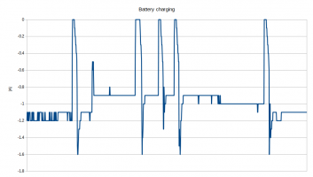
I've made some data logging on the battery charging during the weekend and noticed some unexpected drops to zero in the charge current.
charg1.png
I switched to a self-define battery, and the current drops disappeared. That led me to conclude that there is a problem with BMS CAN communication with the battery. I've made some investigation and found that there is a problem with CAN frame ID 0x453.
I was sending some ASCII chars for battery name:
Code:
can1  453   [8]  44 46 00 00 00 00 00 00
But the inverter expects something different - that frame must contain the total number of 48V packs inside the battery because the commercial HV batteries are made from series-connected 48V(51.2V) modules. So in my case, 360/48 =7.5, and getting the integer part -> 7 modules.
Code:
can1  453   [8]  07 00 00 00 00 00 00 00
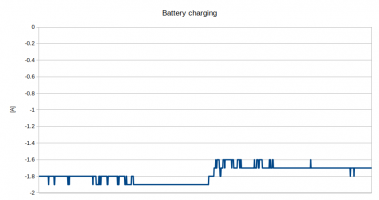
After that fix the charge current looks fine:
charge2.png

I've updated the protocol described in this post and also GitHub software.
 
I've made some data logging on the battery charging during the weekend and noticed some unexpected drops to zero in the charge current.
View attachment 24488
I switched to a self-define battery, and the current drops disappeared. That led me to conclude that there is a problem with BMS CAN communication with the battery. I've made some investigation and found that there is a problem with CAN frame ID 0x453.
I was sending some ASCII chars for battery name:
Code:
can1  453   [8]  44 46 00 00 00 00 00 00
But the inverter expects something different - that frame must contain the total number of 48V packs inside the battery because the commercial HV batteries are made from series-connected 48V(51.2V) modules. So in my case, 360/48 =7.5, and getting the integer part -> 7 modules.
Code:
can1  453   [8]  07 00 00 00 00 00 00 00
After that fix the charge current looks fine:
View attachment 24489

I've updated the protocol described in this post and also GitHub software.
Good news :)

Do you have a time schedulel when you want to try with a fufur DIY LifePO4 battery ?
 
Do you have a time schedulel when you want to try with a fufur DIY LifePO4 battery ?
It depends on many factors. First, I want to build a multi-cell BMS. That is something I'm thinking about for some time. There is a new chip from TI -BQ76952, and it supports up to 16S configuration and has integrated various protection features. With the help of MCU with an isolated CAN interface, it's possible to create a stackable configuration. I've already started a PCB design, but it will take 1-2 months before making some prototypes. I'm going to start a new thread about this.
Regarding LifePO4 cells themselves, they are the right choice for ESS, and I will be happy to use them. But because this is a hobby project, I need to save some money before going in that direction. A rough estimation shows that I need around 2200-2500 euro for a 48 x 100Ah configuration.
So I don't plan an upgrade to LifePO4 battery soon unless I sell my current battery/inverter and start a new build :)
And of course, there are many things to improve in the current system, so now I will focus on that.
You are not afraid to build/manipulate a HV DIY battery ? .... Me yes.... I don't have your experience...... This is why I am really hesiting to go directly wtih HV...
 
The HV battery requires extra precaution and careful manipulation. But this is true for the whole solar system - we have HV from PV panels, the inverter is connected to the grid, and its internal topology is transformerless. There is no galvanic isolation between the grid, battery, and PV panels.
@SeByDocKy, if you don't feel experienced with HV enough, better go with an LV battery inverter.
 
Hi yasko, thanks a lot for your HV can protocol sharing.

I'm going to use your findings to set up a similar project with HV batteries.
I've started with the grid meter part and i'd like to share the protocol, you can add it to your github repo if you find it useful.

The protocol is as follows:


9600bps, 1 stop bit, no parity, no flow control

Master sends every 200ms the following modbus message:

03 03 00 61 00 17 55 F8

03 - ID of slave device
03 - Function code
00 61 - Start register
00 17 - number of registers (23)
55 F8 - CRC


The grid meter replies with the following example message (mine is 1-phase only)

03 03 2E 09 66 00 00 00 00 02 49 00 00 00 00 FA 90 00 00 00 00 FA 90 00 B9 00 00 00 00 00 B9 05 7F 00 00 00 00 05 7F FC 23 03 E7 03 E7 FC 23 13 85 43 62

03 - ID of slave device
03 - Function code
2E - Number of bytes of data (46). The inverter asked for 23 register, so the registers probabily are all 16-bit
09 66 - V-L1 (x10)
00 00 - V-L2 (x10)
00 00 - V-L3 (x10)
02 49 - I-L1 (x100)
00 00 - I-L2 (x100)
00 00 - I-L3 (x100)
FA 90 - signed Active Power L1
00 00 - signed Active Power L2
00 00 - signed Active Power L3
FA 90 - signed Active Power total
00 B9 - signed Reactive Power L1
00 00 - signed Reactive Power L2
00 00 - signed Reactive Power L3
00 B9 - signed Reactive Power total
05 7F - signed Reactive Power L1
00 00 - signed Apparent Power L2
00 00 - signed Apparent Power L3
05 7F - signed Apparent Power total
FC 23 - signed Power Factor L1 (x1000)
03 E7 - signed Power Factor L2 (x1000)
03 E7 - signed Power Factor L3 (x1000)
FC 23 - signed Power Factor total (x1000)
13 85 - Grid Frequency (x100)
43 62 - CRC


I've derived the power figures by comparing the readings with a eastron i had at the same place.

regards,
apr
 
@yasko
BMS and cells are now ordered and I came back to GoodWe hybrid ET/EH inverter.

As I want to use flexible Tariff, is AC charging possible? Do you've experience with that?

May I've also know the German dealer where you bought your GoodWe?
Thanks
 
@apr, If I understand, correctly this is a communication between the Goodwe inverter and its smart meter?
I'm making a map of the Modbus registers of the inverter and will include that info too. Thanks for sharing.
Another interesting finding is the time between messages. It looks that the power control loop works at 5Hz.

@bikefish
The AC charging is possible. There is a dedicated setting - "Economical mode," and you can set up four-time windows for battery charging and discharging. But I don't have long-term experience with this operational mode.
I've ordered my inverter via this online trading platform - Solartraders. I will send more details on PM.
 
Back
Top