High voltage hybrid inverter (GW6000-EH) with EV battery (Chevy Volt)

Hi @curto, the Modbus map is here. I'm not familiar with the SBP5000 inverter and can't guarantee that it uses the same Modbus map as the EH series. With GW6000-EH, it's possible to discharge the battery to the grid, which I think is also valid for SBP5000. I've made some tests with my inverter using registers described in the post you cited. I will write more about this later.
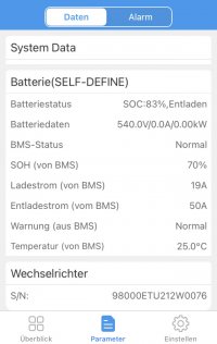
Hi @NexGen, nice setup. These Saft Modules look pretty well. With my inverter, I don't have problems switching between self-define and default batteries. Maybe some parameter is out of range or missing. Your inverter supports a higher battery voltage. Can you post what you are sending to the inverter regarding battery parameters?
 
Last edited:
Hey Yasko - thanks for the response. Yes i am waiting on Goodwe to send me the Modbus map for the SBP5000 which i will have early next week. I will then be able to compare it with yours - i assume there will be differences as the SBP is a retrofit AC coupled battery inverter only - no solar panels.

Will keep you updated.

Craig
 
Hi Yasko!

Here's what I'm sending on the bus and a picture, of what I'm seeing in the PV Master App. Maybe you can check if there's something missing
 

Attachments

  • IMG_9864.JPG
    IMG_9864.JPG
    3.4 MB · Views: 245
  • IMG_9863.jpeg
    IMG_9863.jpeg
    97 KB · Views: 232
@NexGen, your data looks OK, and your BMS status is normal. What are versions of the inverter's firmware and PV Master App?
And what happens when you select a default battery in the app? In my case, when I go to default battery, there are two options - 25Ah and 50Ah:

Screenshot_20210621-195852_PV Master.jpg

After selecting one of them, the App starts cycling, and a few moments later, I get this screen:

Screenshot_20210621-200115_PV Master.jpg

And the inverter switches to the default battery.
 
The Cycling in the PV Master App is the same here - but after some second of cycling it returns to the self define battery without getting that small blue icon next to Default 50Ah...

The inverter is on 616, the PV Master App 4.2.6

Did you first switch to the Default battery and then starting the CanBus Comm or the other way round?
 
@NexGen, It looks like the inverter or app doesn't accept the default battery. My inverter is on the 0313 firmware version, and the app is on 4.2.9, and mine is 1 phase. Yours is 3-phase and with a higher version of ARM firmware (16 vs. 13). Maybe it expects some more parameters. If you have an RS-485 connection (MODBUS) to the inverter, I can tell you some registers to check. Also, check whether you are sending the correct value of battery voltage.
Regarding switching to the default battery - I first start sending data on the CAN bus and then switch via App.
 
Mmmmh it's a little bit curios - i can see 560V as Charging Voltage in the app, but it still stays at 540V...
 
Yes, i can also generate an MODBUS Connection - if you have some hints in this case... everything is appreciated.
 
@NexGen, there are some things to check:
  • read this post, and there is a map between the content of CAN frames and inverter registers.
  • Also, check the BMS registers. There is a brief description is here. The app checks resisters in the range 37002-37009 when performs battery switching.
  • You need to send the correct battery voltage in the CAN frame 0x458, and keep in mind that the inverter measures battery voltage too, and the difference between the two values is a potential problem.
  • I can recommend you mbpoll for MODBUS reading. An example is here:
Code:
mbpoll -a 247 -b 9600 -P none  -r  37000 -c 14 -0 -1  /dev/ttyUSB0

Now I'm running firmware version 0316, and battery switching still works OK. I've made some tests during the weekend and now have a recipe for switching the battery type without the app. I'm going to describe my findings in the next few days.
Meanwhile, I've just finished a PCB design of the new CAN bridge. I've loaded it with tons of hardware features and can't wait to build one. :)

stm-can3.png
 
Last edited:
Thanks Yasko - I got the system running.

Here are some of my experiences...

1. Even if you select the self-defined Battery, the Canbus comes first, so if you select in the app 500V Charge Voltage and you tell him 560V over Can, it takes the 560V and goes up to that limit.
2. The current Battery Voltage isn't a necessary item - it seems that it is needed in this mode only for displaying purposes in the app. But, you need to send something over the bus - zero isn't accepted. In my case - if i send 560V as current voltage, i can see in the app that the Battery voltage is 560V even if the real voltage is at 500V...
3. The Charging is done by using the charge current and the Charge voltage - discharging is done until the Dischargelimit SOC is reached. So i don't know for what reason the discharge voltage is needed?!
4. Charging is also controlled by the Charge current -my BMS decreases the charge current as the current voltage comes to the charging voltage
5. If you send the Frames to fast on the Canbus - you'll get every once in a while a communiction error. By using a delay between the can frames of 100ms - 200ms everything works smooth.

Until know this is one of the best inverters for those second life usage of batteries, in my opinion - the self adaption feature by adapting to the limits of the BMS works really great

Best regards,
 
@apr - can you confirm which GoodWe Mains Meter you have - they appear to have 3 - GM1000D - this is apparently the one i will be getting, GM1000 (the only difference i can see is that one has dual CTs) and GM3000 which appears to be the 3phase unit - presumably with 3 CTs.

I assume they would all present roughly the same modbus registers.

Craig
 
@curto, the GW6000-EH comes with GM1000 smart meter with a single CT. GM1000D (with dual CT) is for retrofit systems. Some description is here.
I've just updated the MODBUS map for the inverter in my repository. I've cleaned it, and now it is more accurate. The registers starting with 3xxxx are read-only ones for monitoring. The control of the inverter is done via the 4xxxx address space, but my information is incomplete here.
 
@yasko - thanks for that will check the Repo. As i am getting the AC coupled inverter as a retrofit i will end up with the Dual CTs.

I am still waiting on my Modbus map for the SBP5000 from Goodwe

Craig
 
@yasko - yes that is much tidier thanks.

I will contribute once i receive all my gear - just waiting to hear from @apr to see if he is happy to share his arduino code or if i need to go out and contract a freelancer to write it for me

Craig
 
Guys,

OK got all the gear and in and running (in a very basic fashion) - Should i move this to another thread - as although it is about Goodwe inverters it is not about HV DIY battery packs ?

Craig
 
OK just for anyone else searching on here - the inverter does not support Modbus over UDP/TCP.

It does respond on port 48899 with something - which i will wireshark tomorrow as this is how the PV Master app talks to it.

May end up reverting to using RS485

Craig
 
Last edited:
OK just for anyone else searching on here - the inverter does not support Modbus over UDP/TCP.

It does respond on port 48899 with something - which i will wireshark tomorrow as this is how the PV Master app talks to it.

May end up reverting to using RS485

Craig
OK got something happening here

PV Master when it starts up does a UDP query on port 48899. All of the inverters respond to this with their IP Address, their MAC address and a short identifier - which appears to be either an internal model number or something to do with the ethernet card - either way you end up with the same response HF_E20 and this is what shows in the main screen of PV Master so no way to differentiate which inverter is which.

You then select one and it goes into the config screen where it shows the Serial Number so now you know which inverter you are working on. From here it is all UDP 8899 communication backwards and forwards.

I have used the Home Assistant Python project


To do some basic scanning - however the inverter appears to be returning lots of truncated packets and then dropping off the network for 30 seconds or so.

I suspect there is an issue with LAN Dongles (that i used to replace the Wireless dongles) not being fully supported in the SBP range - i will test that shortly by swapping out one of the LAN dongles and reinstall the wireless unit and see if the results are any different.

Based on other docs i have found on the Goodwe site they indicate that Modbus TCP/UDP is not available on the SBP and that i will need to use RTU - but they are obviously talking to it with the PV Master app so i will continue trying at this point.

Craig
 
Hello everybody!
I searching three phase hybrid inverter GoodWe witch works with diy high voltage battery and raspberry pi. Thanks for help!
 
Hey Guys,

Just a further update on my progress with my 3 x SBP5000 units. I have been working with some guys associated with the Home Assistant project and we have made good progress.

Using the UDP 8899 protocol and the older AA55 implementation which seems to be used by the ES/EM and SBP families we are able to control the inverters.

They do not support Modbus over the LAN/WIFI interface - but do seem to support it over the dedicated EMS port - but using a completely different register set to the ET units.

At the moment i have decompiled the APK file from Android and then dont some extensive capture of packets from the interaction between the inverter and the App.

At this stage i am leaving the inverter in ECO mode and using slot 1 and slot 2 for times - i have set slot 1 to operate between 00:00 and 11:59 and slot to between 12:00 and 23:59.

I can dynamically send the inverters into charge/discharge mode and vary the amount they are exporting/importing - i am doing this on a 5 second window at this stage and have not experienced any issues with comms with the inverters.

The one issue that i have that is outstanding at the moment is that at 3am (which has happened two days in a row now) the inverters refuse commands to discharge dynamically for no good reason (although of them are at slightly different SOC levels) and it is only around 500w i am asking for so it is nothing to do with this.

The error that comes up on PV Master is that their is an error in the discharge definiton and then the inverters slowly taper off their output.

Once my app then tells them to start charging again the next day (once we have excess solar) they continue operating with no other changes. I need to investigate this further and try to understand what is happening.

My next thing to do is to take over the control of the Energy meters and see if i can send fake data to the inverter whilst leaving it in General mode - i should have this done tomorrow and can then report back

Craig
 
@yasko, just a further update for your spreadsheet

I can confirm that the GM1000D (Dual CT) uses the same protocols as defined earlier by @apr

The Inverter (SBP5000) sends out the following every (approx 200ms)

Request from Inverter to read Energy meters
03 03 00 61 00 17 55 F8

03 - ID of slave device
03 - Function code
00 61 - Start register
00 17 - number of registers (23)
55 F8 - CRC

It looks like all of the energy meters have the same slave address of 03 - mine does not have anyway to change it - unless it is done through the front USB port.

The Meter responds to the request from the Inverter with 46 Bytes - will confirm shortly if they are the same as @APRs findings. (May be different as this unit has two CT clamps one for Solar input and one for Grid

Craig
 
Back
Top