
Stefanseiner
Member
- Joined
- Apr 16, 2020
- Messages
- 136
it may works below 40V. Yesterday I booted my JKBMS with 36V. Maybe it can run with lower voltage but I haven't tested it


Hey Buddy, Take a look of that, After few weeks working flawless, Stop to read the BLE, doing some checks found a error in the plugin..Try sudo python3 setup.py install
I may have left that part out.
pi@JK-BMS-Pi:~ $ sudo telegraf -debug
2021-02-09T05:06:04Z I! Starting Telegraf 1.17.2
2021-02-09T05:06:04Z I! Using config file: /etc/telegraf/telegraf.conf
2021-02-09T05:06:05Z I! Loaded inputs: cpu disk diskio exec kernel mem processes swap system
2021-02-09T05:06:05Z I! Loaded aggregators:
2021-02-09T05:06:05Z I! Loaded processors:
2021-02-09T05:06:05Z I! Loaded outputs: influxdb
2021-02-09T05:06:05Z I! Tags enabled: host=JK-BMS-Pi
2021-02-09T05:06:05Z I! [agent] Config: Interval:30s, Quiet:false, Hostname:"JK-BMS-Pi", Flush Interval:10s
2021-02-09T05:06:05Z D! [agent] Initializing plugins
2021-02-09T05:06:05Z D! [agent] Connecting outputs
2021-02-09T05:06:05Z D! [agent] Attempting connection to [outputs.influxdb]
2021-02-09T05:06:05Z D! [agent] Successfully connected to outputs.influxdb
2021-02-09T05:06:05Z D! [agent] Starting service inputs
2021-02-09T05:06:15Z D! [outputs.influxdb] Buffer fullness: 0 / 10000 metrics
2021-02-09T05:06:25Z D! [outputs.influxdb] Buffer fullness: 0 / 10000 metrics
2021-02-09T05:06:35Z D! [outputs.influxdb] Wrote batch of 13 metrics in 44.254286ms
2021-02-09T05:06:35Z D! [outputs.influxdb] Buffer fullness: 0 / 10000 metrics
2021-02-09T05:06:45Z D! [outputs.influxdb] Buffer fullness: 0 / 10000 metrics
2021-02-09T05:06:48Z E! [inputs.exec] Error in plugin: invalid character 'C' looking for beginning of value
2021-02-09T05:06:55Z D! [outputs.influxdb] Buffer fullness: 0 / 10000 metrics
2021-02-09T05:07:05Z D! [outputs.influxdb] Wrote batch of 18 metrics in 29.179523ms
2021-02-09T05:07:05Z D! [outputs.influxdb] Buffer fullness: 0 / 10000 metrics
2021-02-09T05:07:14Z E! [inputs.exec] Error in plugin: invalid character 'C' looking for beginning of value
2021-02-09T05:07:15Z D! [outputs.influxdb] Buffer fullness: 0 / 10000 metrics
2021-02-09T05:07:25Z D! [outputs.influxdb] Buffer fullness: 0 / 10000 metrics
2021-02-09T05:07:35Z D! [outputs.influxdb] Wrote batch of 18 metrics in 70.553285ms
2021-02-09T05:07:35Z D! [outputs.influxdb] Buffer fullness: 0 / 10000 metrics
2021-02-09T05:07:43Z E! [inputs.exec] Error in plugin: exec: exit status 1 for command '/home/pi/jkbms.py': Traceback (most recent call last):...
pi@JK-BMS-Pi:~ $ sudo python3 /home/pi/jkbms.py
Traceback (most recent call last):
File "/home/pi/jkbms.py", line 458, in <module>
jk.getBLEData()
File "/home/pi/jkbms.py", line 309, in getBLEData
serviceId = self.device.getServiceByUUID(btle.AssignedNumbers.genericAccess)
File "/usr/local/lib/python3.7/dist-packages/bluepy/btle.py", line 488, in getServiceByUUID
rsp = self._getResp('find')
File "/usr/local/lib/python3.7/dist-packages/bluepy/btle.py", line 407, in _getResp
resp = self._waitResp(wantType + ['ntfy', 'ind'], timeout)
File "/usr/local/lib/python3.7/dist-packages/bluepy/btle.py", line 362, in _waitResp
raise BTLEDisconnectError("Device disconnected", resp)
bluepy.btle.BTLEDisconnectError: Device disconnected
# # Read metrics from one or more commands that can output to stdout
[[inputs.exec]]
# ## Commands array
commands = [
"/home/pi/jkbms.py",
]
#
# ## Timeout for each command to complete.
timeout = "20s"
#
# ## measurement name suffix (for separating different commands)
name_suffix = ""
#
# ## Data format to consume.
# ## Each data format has its own unique set of configuration options, read
# ## more about them here:
# ## https://github.com/influxdata/telegraf/blob/master/docs/DATA_FORMATS_INPUT.md
data_format = "json"
#!/usr/bin/python3
from bluepy import btle
import math
import json
EXTENDED_RECORD = 1
CELL_DATA = 2
INFO_RECORD = 3
getInfo = b'\xaa\x55\x90\xeb\x97\x00\x00\x00\x00\x00\x00\x00\x00\x00\x00\x00\x00\x00\x00\x11'
getCellInfo = b'\xaa\x55\x90\xeb\x96\x00\x00\x00\x00\x00\x00\x00\x00\x00\x00\x00\x00\x00\x00\x10'
name = 'wtfsection'
model = 'JK-B2A24S'
mac = '3C:A5:19:7B:23:FE'
command = 'command'
tag = 'Powerwall_1'
format = 'influx2'
out=dict()
c_high=0.00
c_low=10.00
c_diff=0.00
I have the JK-DZ11-B2A24S, the one with RS485 comms. I first tried the QR code on the label and got fed up, so I looked at www.jkbms.com and that filled in a few missing pieces...
It requires >2.4v on B1 in order to wake up
As well as at least 40V total voltage
So I did some further testing while running on 3s lifepo4, and it doesn't mind if B1 is temporarily disconnected.
So I then reconnected my 24s wiring harness, again it doesnt wake up, I cut B1 wire in half and added an AA battery in series with my fingers (effectively it sees B1 around 3.5V), wait for the balancer to fully boot up and then remove AA battery and twist B1 wires back together.
It is now alive... I then find my harness has high resistance on an number of wires that the balancer warnings me about and means I cant turn the active balancing feature on yet. (the harness was from a different monitor setup which I cut at the plug soldered leads onto JK loom, this will need replacing...)
Getting closer to a solution...
Last issue I might have is that I cannot set the shut down voltage to below 2V, if it will self shutdown under 48V then it is clearly not suitable to keep going (which would mean a manual AA battery wake up everytime I have a few cloudy days)
Are there any people out there running Lead Acid / Lead Carbon or even LTO (which has a slightly higher cell voltage but still potentially a problem) on these active balancers???
Wow thank you for this ... I have one of these with bluetooth/can/485 and have asked the company several times for protocol info on them and got nothing.Here's the RS485 protocol that I was able to obtain for the JK-B1A24S. I don't have the board with this interface so I can't use it but is up for anyone else that could use it.
View attachment 5
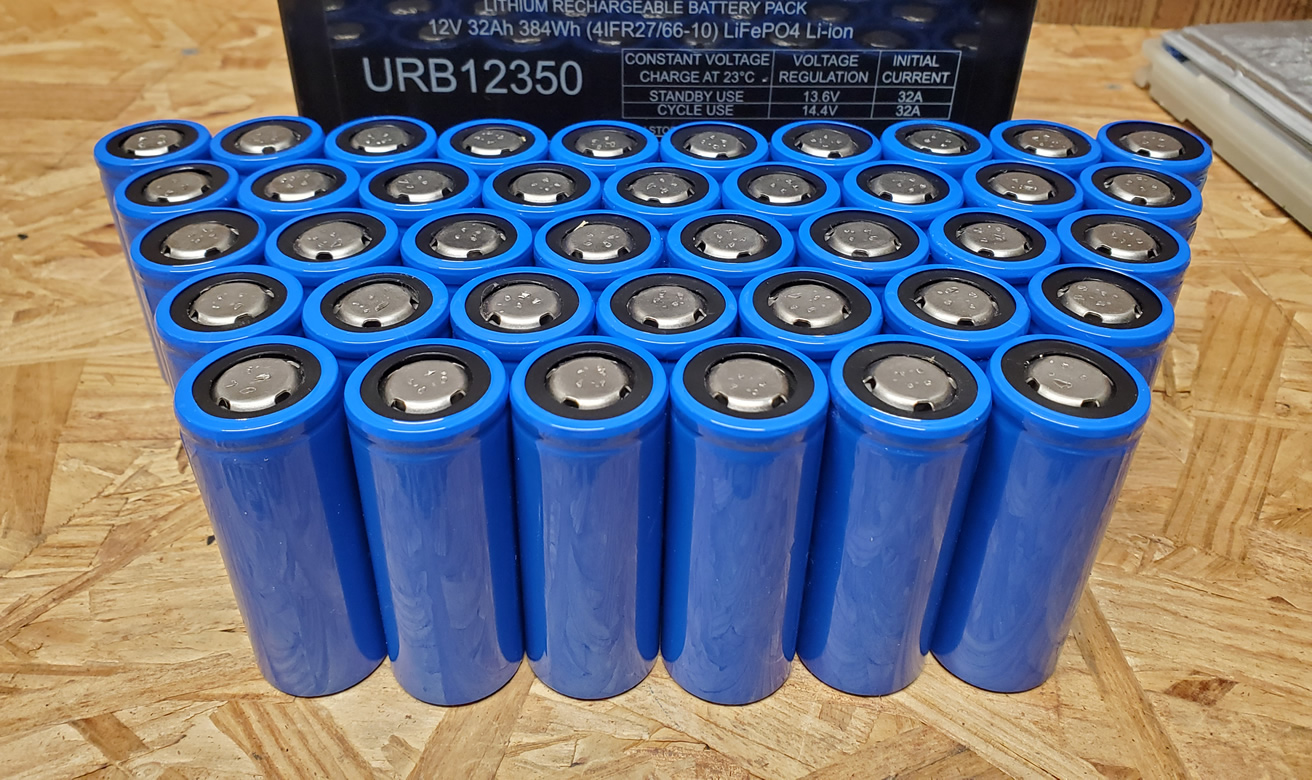
So I am using a couple of this new versions of the JK-B2A24S-15P
Two at my actual system with 2x 14s60p on a Infini E5.5K, and another two on my second system which is still in building process with 2x 14s120p on a MPP MPI 10k.
View attachment 16000
View attachment 17011
Both systems are in my backyard and I would like to monitor them from inside the house
View attachment 11499
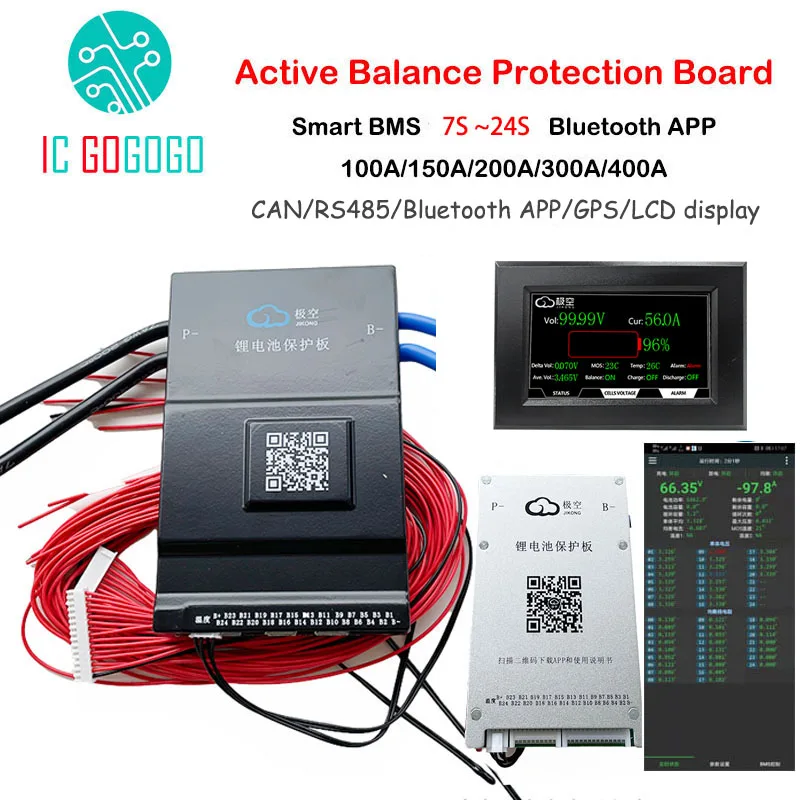
The new ones come with CAN and RS485
View attachment 16860
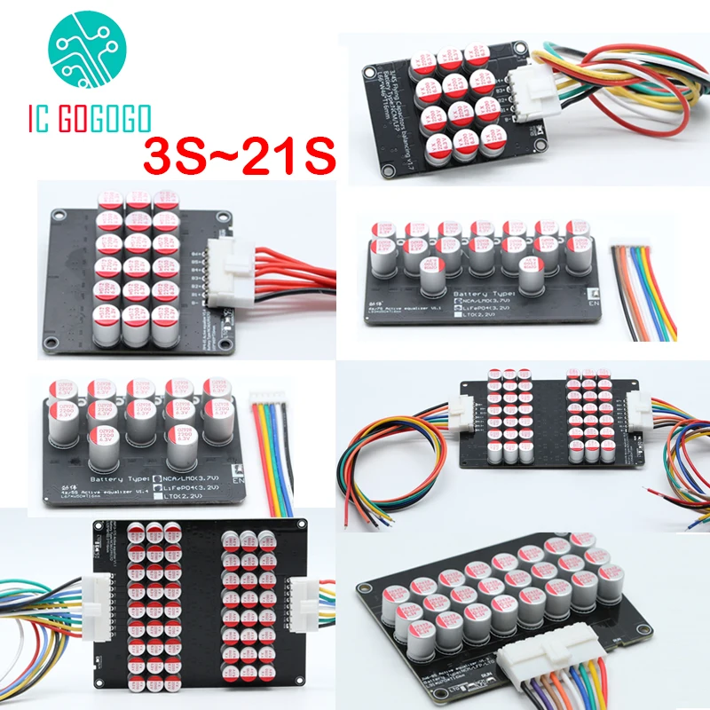
and an option for addional modules
View attachment 22003
not sure, for what you will need them. Asked the seller and the answer was "to connect with the computer" but there are no USB or ethernet connectors on it, so...
View attachment 11406
View attachment 13014
Two questions:
1.) does anybody know if a need this modules to connect the BMS with a computer or can I directly use the RS485 / CAN ports at the bms itselfes?
2.) how would I proceed the best way to get the BMS data in my house?
I have CAT7 network cables to both inverter locations and would prefer some communication over ethernet. For the inverters I am using some Modbus -> Ethernet adapters.
I do not own an Pi and would prefer to avoid one because I am planing to install an "real" server with ESXi running 24/7 at my cellar. Network switch and hardware is there, just not setting up the stuff for now.

 diysolarforum.com
 github.com
github.com
github.com
First of all the attached PDF is the wrong version. You have the JK-BD6A20S10P which I believe is the BMS version, while the document is the balancer version only. So the registers might be different. I don't have either version with the RS485 or canbus so I won't be able to help much.
Ugh I just wrote a whole thing about modbus then realized that this isn't a modbus protocol. It looked so much like a modbus protocol! Just removed all that content.
But check out jblance's github repository. He has built a python program that communicates to the BMS. I believe he started work on the RS485 protocol. It used to be a separate program but he merged it into his main mpp-solar program.

GitHub - jblance/mpp-solar: Python package to communicate to MPP Solar PIP-4048MS inverters (and similar)
Python package to communicate to MPP Solar PIP-4048MS inverters (and similar) - jblance/mpp-solar
github.com
Try contacting this seller. That's where I bought mine from and where I obtained some of the documentation from.
6.66US $ 26% OFF|Jikong 1a 2a Active Balance Bms Battery Protection Board 7s ~ 24s 100a 300a Can Rs485 App Lifepo4 Li-ion Lto 48v 8s 16s 20s 72v - Battery Accessories & Charger Accessories - AliExpress
Smarter Shopping, Better Living! Aliexpress.comwww.aliexpress.com
 diysolarforum.com

