LG Chem Module Build

Charger arrived. Looks good, but I am still waiting for the postal service to deliver the BMS (went with REC) so I can test out charging. Planning to use 4x 12V headlight bulbs in series for the drain test.

I'm wondering about cabling now and am looking for advice. I'm likely to go with 2/0 for my 30+ parallel connections, ea. one ~8" long. Trying to decide what kind of cabling will be best. I read through a few forums on cabling and seems like some prefer marine grade tinned copper cabling, while others prefer welding cable. I bought 1 ft. of this stuff, flex-a-prene welding cable 2/0, to see what it feels like, and it seems good for my purposes - no UV exposure, not marine environment (although it will be in a shed). I'm also trying to figure out what I will need for inspection - does it generally have to be UL rated? - maybe best to check with AHJ about this detail? Since I'm going to be fabricating so many cables, I am trying to avoid the situation where they ask me to redo.

Input appreciated.

[EDIT May 16: Just reading through the 2018 Canadian Electric Code (CEC) and found this restriction on cabling: "flexible building-wire-type cables are available and are suitable for this use [i.e. for connecting to battery terminals - I believe both for intra-battery connections and for battery to inverter connections]. This Code does not permit welding and battery cables to be used for this purpose" (CEC 2018, Appendix B, Rule 64-810, p. 709). So, "flexible building wire type cables" it is.
 
Last edited:
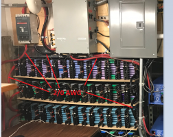
I used 2/0 AWG welding cable - its a good choice for battery connections/cabling. I used 2/0 lugs to create my own cables - https://www.amazon.com/gp/product/B073CLCXGH/ref=ppx_yo_dt_b_search_asin_title?ie=UTF8&psc=1 and ordinary nuts/bolts.

The purchased components (Midnite Classic Controllers, AIMS inverter, boxes, circuit-breakers, etc) were all ETL (or UL) but a DIY battery cannot be UL :) There's the question of conduit (DC must be in conduit in my jurisdiction). Panels -> Controllers were all in proper conduit but I didn't do that for short lengths (5 feet) - e.g. battery pack connections and between the battery and control-box / inverter. My electrician of record just didn't know solar / battery stuff very much so it was 'a worry' going into the inspection.

However, the city inspector didn't even look at the DIY battery, didn't ask any questions about it etc. He was only concerned about where the power (from the inverter) went. Since mine is off-grid, all I did was point to a properly wired outlet on a UL Go-Power ATS and he said OK :)

1618795543251.png
 
Last edited:
Nice set-up. Must have taken some time to get those 18650's assembled. I took your cue and ordered enough Selterm 2/0 lugs to do the whole battery bank and will keep an eye out now for the welding wire to go on sale. I've still got a few things I can work on in the meantime.

Just contacted my AHJ today and learned I'll be inspected under the 2018 Canadian Electrical code, but they're upgrading in the Fall to the 2021 Canadian Electrical Code. I'm not sure what this means for the battery - maybe I'll need to get everything done asap . . . before they upgrade. Also spoke with my electrician of record (at least he will be once I get the permit submitted) today to see if we can determine more details about what each version of the code will permit for the battery. I'm really hoping I end up with an inspector like yours.

[EDIT May 16: I got my hands on the 2018 CEC today, and this is correct - the requirement for using certified batteries is not here, but from what I found in reading about the 2021 CEC, I am pretty sure that requirement is there in the 2021 CEC. So, I guess no more permitted battery module installations in Canada wherever 2021 CEC has been adopted.]

The REC BMS finally arrived this evening. Canada Post is pretty slow these days, but now I'll be able to figure out the BMS and get it hooked up - hoping by end of this week - so I can start running some charge and capacity tests on the one module that's now all ready to go. Thanks for your quick reply - big help to keep me on track.
 
Last edited:
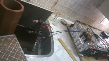
Update here . . . been making progress: 1st module completed for testing, found voltage drop of ~.02V in cell group #4, which is right at the connection I made between the 4s block and the 10s block. Attached 2/0 cable and found that the problem disappeared, so now I'll double up my copper bus and re-test. Just hooked up an inverter for bench testing, since my diy auto headlamp drain was taking too long to drain the battery for testing. Here are some pics:


WP_20140525_08_13_52_Pro[1].jpgWP_20140525_08_14_13_Pro[1].jpg

Here's a close-up of the same troublesome connection on another module - this also will have to be doubled up, though:

WP_20140525_08_16_09_Pro[1].jpg 400bird has a nice idea in another thread about how to make bus bars look good.

Here's my attempt at making an inexpensive DC load for testing - 4X auto headlights take just over 200 Watts - ended up being too small a load:
WP_20210502_17_39_56_Pro.jpgWP_20210502_17_40_08_Pro.jpg GMXnow gave me the idea of using 12V auto lights.

Anyways, thought I'd update.
 
Looking good! I've got to load up some more pictures of my progress.

If you had a 20 millivolts drop across your bus bar, did you compare to the factory bus bars?
What was your load at the time?

It looks like you attach the bus bar with two 1/4" or 6mm bolts? I went with 3 smaller #8 screws. I haven't been able to load test yet, so I don't know if that's any better.

Also, what is the thickness of your copper?

If you're looking for a resistive load, you could rewire a small space heater. The fan will probably only run on AC, but you can separate out the heater coil. That should be about a 500 watt load? Depending on the heater element and your battery voltage. You'd still need to run the fan on AC to keep the element from burning out.
 
Thanks. Yes, I'd be interested to see your buses installed.

So, I was charging the module using a 10 amp charger when I saw the difference. My description of the 20 mV drop needs correction, though. The 20 mV is the difference in cell group #4's voltage as compared with the rest of the cell groups in the module - measured by the BMS. The voltage drop was, I believe, 30 mV as compared with 20 mV voltage drop on the rest of the bus bars. I am certain, though, that the voltage drop (measured also when charging at this 10 amp level), was 1.5x the voltage drop measured on the other bus bars.

Yes, these are 1/4" bolts. I used silicon bronze hardware, and was a bit concerned I'd strip anything smaller made from this alloy. That thought could be wrong, but I can say that I have had no trouble, and have been torquing to ~80 in. lbs. I can see using 3 #8 screws, too, because it is tight in there and you can probably get closer to the base of the tab connection using smaller fasteners. I ended up refurbishing an old dentist's drill I had to give me better control, and it does the trick nicely. The elements of that drill that work well are 1. a flex-shaft, and 2. a pedal control with variable speed - the further you push the pedal, the faster the speed. This is compared with my cheap dremmel, which has only 3 fixed speed options and no flex shaft.

Thickness of my copper is ~.7mm, which is about the original bus bar thickness. I saw that you have 1mm, which is probably better, especially at the connection that has given me trouble. One other thing I will mention is that I found a multi-tool really useful in doing the module surgery. It gave me better control and precision than the dremmel disks, especially because it allows for plunge cuts of the plastic.

Ahah. Space heater with the coil wired for DC. That is a good idea. Wish I had asked you a few weeks back.:)
 
Last edited:
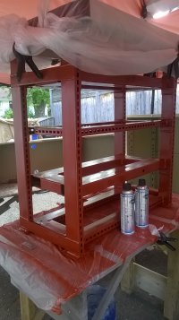
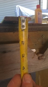
So, been making progress, but of course more slowly than I want. Here's the steel rack I welded up to hold the modules. The red paint is an electrically-insulating varnish that also blocks moisture/prevents rust - I'm not sure how abrasion resistant it is, though. Here's a close-up of the varnish spray can in case anyone has a use for it - there are other brands out there - this brand requires very thorough prep of the metal, which took much time - not sure if they all require clean, bare metal:

WP_20140526_22_26_23_Pro.jpgWP_20140526_22_25_58_Pro.jpgWP_20140526_22_26_08_Pro.jpg

Here's some copper bus bar I picked up at the scrap yard and cleaned up - I paid ~$30 for 5lbs., which is way more than I'll need for this build. Scrap yard is one way to get electrical-grade copper for anyone on a budget. The dimensions of this bar are .25" thick, 2" wide, ~30" L. I'm planning to tin the whole bar and then make (2x) 8" bus bars, one for ea. of the -ive and +ive sides of the battery bank. I still have to figure out the details of how to insulate the bus - some type of insulating stand-offs. If anyone has a suggestion for that, please let me know:


WP_20140529_20_49_36_Pro.jpgWP_20140529_20_50_20_Pro.jpgWP_20140529_21_03_50_Pro.jpgWP_20140530_04_04_41_Pro.jpg
 
Last edited:
Wow, I wish I could get good deals on a nice piece of copper like that! I do need to redo my B+ bus bar and make one for B-

My current B+ bar is insulated in unused areas with large red heat shrink, they make sizes up to at least 2 inches.

If you are looking for insulated mounting options. I'd recommend googling "red isolator stand off" tons of choices and ideas. I have been tempted to 3d print something, but if the bus bar got warm the 3d printed piece would melt immediately...

Screenshot_20210624-191921.png
 
Great. Will take a look. Definitely want something like this rather than the 3-d printed option. Thanks!
 
Back
Top