MegaCellCharger mods, tuning and reverse engineering

Oleksii

Member
Joined
Mar 18, 2020
Messages
116
Hi all!

First of all I have a lot to share as for MCC, with photos of course, but currently I want to start from a topic to pay attention from developers ad possibly get a fix/improvement.
It's about charge and discharge current measurement precision an adjustments.
I've started from measuring current. First I've checked and my DMM measures current correctly by comparing it with lab power supply and YR1035+ measured 4.84R resistor and then measured voltage drop over it 1.687V - I got the same reading of ~348 mA current (Ohm's low 1.687/4.84=0.3485).Tried higher values - the same:
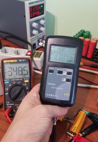
DMM-check.jpg
Then I made this simple "connector" from a small piece of material, used to produce 2 side PCB. It allowed me to "interrupt" cell circuit easily and quickly in any device and measure current in a stable way:
current-connector.jpg
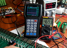
Then I started "per slot" measurement, which looked this way:
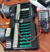
checking-MCC.jpg
(yes, you have spotted those FANs of left :D, I know, I'll share info about them soon)

I noted current after 1 minute of started change/discharge, to get it stabilized as some resistor inside MCC getting more warm, possibly change resistance a little.
I've to note here what while on MMC current was INcreasing a little during the minute, on DMM it was opposite - DECreasing a little, but after 1 minute values were "in sync" and were slowly decreasing together with the same rate. So 1-2 minutes delay was a proper thing, I suppose.

I made 4 cycles (change/discharge and before/after correction of CcO/DcO).
CcO/DcO - are Charge correction factor (%) and Discharge correction factor (%) in MegaCellMonitor software
Here are results:

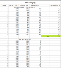
ch.png

disch.png

I spotted previously that MCC shows increased cells capacity measurement, so values of current was not surprising for me.
Also I know from other MCC users the same.

Summary: each slot has its own drift or precision for charge and discharge. Calculated average for all slots - probably an ideal way to find out what are the best correction factors for your own MCC.

‼️‼️‼️ What I dream of currently - that MCC have to provide a way to set CcO/DcO per slot basis. I'm sure its really possible and this way it's possible to adjust each slow and hopefully get were consist reading of capacity! ‼️‼️‼️


I saw that MegaCellMonitor sends some extended JSON when staring individual commands for slots (POST to /api/set_cell) where CcO/DcO were included together with CmD (command what to do). I was hoping that it can work this way, but unfortunately it's just extra data included to JSON, which probably is ignored by MCC. Used command like this:
Bash:
curl http://10.33.0.66/api/set_cell -d '{"cells": [{"ChC": false, "CiD": 0, "MaV": 4.25, "StV": 3.6, "MiV": 2.8, "DiC": 1, "CmD": "ach", "LmV": 0.3, "LcV": 3.6, "LmD": 1.1, "LmR": 90, "McH": 240, "LcR": 1000, "CcO": -50, "DcO": -50}]}'
but it does not set CcO/DcO in any way.

Also, default values in MegaCellMonitor for factors are 1. I've tried to set 0 (zero) using shell commands (see below) but looks like internally it's still set to 1.
And on reading an absolute step between 1% and -1% was ~20 mA (we work with ~1A current all the time) which confirms that it's 2% difference. Because between -1% and -2% the step is ~10 mA. The same for 1% and 2% - ~10mA step.
It means that correct default values for MegaCellMonitor and MCC should be 0 (zero) but not 1. But that's minor thing.

Btw, I changed CcO/DcO using this shell command, easily, event right during charge or discharge procedure on a slot, which caused updated/recalculated values reading immediately.
Bash:
curl http://10.33.0.66/api/set_config_info -d '{"LmR": 90, "CcO": -7, "DcO": -5, "LmV": 0.3, "LcV": 3.6, "LmD": 1.1, "ChC": false, "MaV": 4.25, "StV": 3.6, "MiV": 2.8, "DiR": 1000, "MaT": 45, "DiC": 1}'

Commands for start charge and discharge on all slots and monitor values (on another window) are:
Bash:
curl http://10.33.0.66/api/set_cell -d '{"cells": [{"CiD": 0, "CmD": "ach"}, {"CiD": 1, "CmD": "ach"}, {"CiD": 2, "CmD": "ach"}, {"CiD": 3, "CmD"
: "ach"}, {"CiD": 4, "CmD": "ach"}, {"CiD": 5, "CmD": "ach"}, {"CiD": 6, "CmD": "ach"}, {"CiD": 7, "CmD": "ach"}, {"CiD": 8, "CmD": "ach"}, {"CiD": 9, "CmD":
"ach"}, {"CiD": 10, "CmD": "ach"}, {"CiD": 11, "CmD": "ach"}, {"CiD": 12, "CmD": "ach"}, {"CiD": 13, "CmD": "ach"}, {"CiD": 14, "CmD": "ach"}, {"CiD": 15, "Cm
D": "ach"}]}'


curl http://10.33.0.66/api/set_cell -d '{"cells": [{"CiD": 0, "CmD": "adc"}, {"CiD": 1, "CmD": "adc"}, {"CiD": 2, "CmD": "adc"}, {"CiD": 3, "CmD": "adc"}, {"CiD": 4, "CmD": "adc"}, {"CiD": 5, "CmD": "adc"}, {"CiD": 6, "CmD": "adc"}, {"CiD": 7, "CmD": "adc"}, {"CiD": 8, "CmD": "adc"}, {"CiD": 9, "CmD": "adc"}, {"CiD": 10, "CmD": "adc"}, {"CiD": 11, "CmD": "adc"}, {"CiD": 12, "CmD": "adc"}, {"CiD": 13, "CmD": "adc"}, {"CiD": 14, "CmD": "adc"}, {"CiD": 15, "CmD": "adc"}]}'

watch -n1 'curl http://10.33.0.66/api/get_cells_info 2>/dev/null | egrep "amps|capacity|voltage"'

p.s. stay tuned, there are even more interesting parts of MCC I want to share ;)
p.s.2 btw, that was me who discovered a bug on MCC that it always added an extra ~100mAh capacity to each slot on mCap command. Devs were really good to fix it very fast.
 
Last edited:
Let me say a few words about voltage reading, as it's related to possible improvements in a similar way.

MCC looks like (I guess) uses the same ADC pin on main chip ESP8266, using HP4067 chips (CD74HC4067 - Analog Multiplexer/Demultiplexer) to connect cells for reading.
So, voltage on all slots are 100% the same, which is nice.

But on my MCC difference between MCC and DMM I trust is 0.018v. MCC shows higher value than DMM.
I'd be happy if there would be a way to have a new settings - Voltage correction factor, in %. It could be a global option, as no needs to heave it per slot.
It should accept float values, to be able to set 0.1% as a value. Such precision should be enough.

Will try to ask devs to implement such setting.
 
Last edited:
Hello, her are my Cal Corection Tests of my 10 Chargers.
 

Attachments

  • MegaCellCharger_Calibration.xls
    69 KB · Views: 183
Well done. In the Excel spreadsheet I would add the possible offset due to multimeter's precision, because in any case readings could float up or down, for e.g. ±1%. The first mAh value reading 1004 could be 993,96 up to 1014,04.
 
But on my MCC difference between MCC and DMM I trust is 0.018v. MCC shows higher value than DMM.
I concur to the ≈ 0.018v difference between my verified RC3563 and the MCC which shows mostly higher.
On my last batch of 1375 cells all tested with the MCC and ending voltages copied from the MCM into Excel then verified with the RC3563
I come up with an average difference of 0.016v
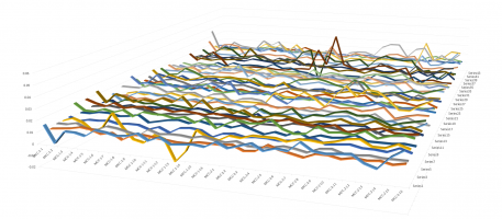
1613756747355.png
When graphed there is definitely a slot to slot comparison. As in each slot has its own variation of a voltage difference.
The graphs makes it quite evident. Although the differences are very minute they still could be a go/no-go when measuring for SD cells especially if you never measure the true exit voltage which also tends to be not really ≈4.2v or whatever you set storage voltage too.
1613756394400.png1613757765936.png
MCC exit voltages differences between slots is also an issue MCC 1 Slot 2 is very apparent.
These are the voltages copied and pasted from the MCM interface not my voltage observations.
1613758829106.png
Wolf
 
#BUGREPORT

Yeah, I'll use this #BUGREPORT tag to indicate that and to simplify searching here, I as I'm going to report a few of them really soon.
As I you know I like when everything works correctly and if it's not I start to find a root cause. MCC is not an exclusion, so let's go to the topic :)

Summary: changed ESR reading on firmware V4.3.0.11 is really bad and may lead to wrong results!

Input conditions: recent MCC revision in plastic case (with single INA219 ADC), discharge current is 1A is MCC settings.

Details: In previous firmware V4.1.8 MCC was ESR measuring this way:
measure voltage without load, apply discharge, wait for 6 seconds (making 12 readings with 500 ms intervals - just an internal logic of polling all 16 slots), measure voltage again, then make calculation: (Vstart-Vend)/Idisch = R (ESR) in ohms.

That gave pretty consistent readings on any slot and every time. But disadvantage is that cells will low capacity could show quite high ESR.
Example:
Cell capacity, mAhReal ESR (measured on YR1035+), mRESR measured by MCC V4.1.8 (with improved neg spring) , mR
25037190
130023115
25001668


After firmware upgrade to V4.3.0.11 I observed other values (comparably lower) reading and, what is very bad, they were very inconsistent !!!
What happened?

Ok, I checked debug (listening MCC's TCP port 8888) and spot messages which were not there on previous firmware. Let me post them here, shortened:
Code:
000 03:20:22.808 - (Debug) - CiD: 15 SetEsrRunning: 1
000 03:20:22.809 - (Debug) - Current DiR: 1000
000 03:20:22.811 - (Notice) - Setting DiR: 200
000 03:20:22.812 - (Notice) - Class parameter DiR: 200
000 03:20:22.813 - (Debug) - Previous DiR: 1000 Current DiR: 200
000 03:20:22.816 - (Warning) - ClearCellDischargeData - reseting dischargeCapacity
000 03:20:22.819 - (Notice) - Setting fan speed to FULL!
000 03:20:22.822 - (Notice) - Wait cycle count configured to: 26
000 03:20:23.330 - (Debug) - CiD: 15 - ProcessWorkflow: eWorkflow::Start_ESR_mcap - countdown wait cycles (26 / 26)
... 19 repeats ....
000 03:20:33.554 - (Debug) - CiD: 15 - ProcessWorkflow: eWorkflow::Start_ESR_mcap - countdown wait cycles (6 / 26)
000 03:20:33.572 - (Debug) - CiD: 15 - V1: 3.76 - i1: -23.64Stage 1 of ESR completed.
000 03:20:33.574 - (Debug) - CiD: 15 SetEsrRunning: 1
000 03:20:33.575 - (Notice) - Setting DiR: 1000
000 03:20:33.576 - (Notice) - Class parameter DiR: 1000
000 03:20:33.577 - (Debug) - Previous DiR: 200 Current DiR: 1000
000 03:20:34.052 - (Debug) - CiD: 15 - ProcessWorkflow: eWorkflow::Start_ESR_mcap - countdown wait cycles (5 / 26)
... 3 repeats ....
000 03:20:36.092 - (Debug) - CiD: 15 - ProcessWorkflow: eWorkflow::Start_ESR_mcap - countdown wait cycles (1 / 26)
000 03:20:36.589 - (Debug) - CiD: 15 - ProcessWorkflow: eWorkflow::Start_ESR_mcap - calculate
000 03:20:36.600 - (Debug) - CiD: 15 SetEsrRunning: 0
000 03:20:36.602 - (Debug) - previous DiR: 1000 Current DiR: 1000
000 03:20:36.603 - (Notice) - Setting DiR: 1000
000 03:20:36.604 - (Notice) - Class parameter DiR: 1000
000 03:20:36.605 - (Debug) - Reset previous DiR: -1 Current DiR: 1000
000 03:20:36.618 - (Debug) - CiD: 15 - V2: 3.74 - i2: -999.01Stage 2 of ESR completed.
000 03:20:36.620 - (Debug) - CiD: 15 - Volt drop: 0.02 - amps: -975.37
note - ESR in JSON reported by MCC in this particular cell measurement was "esr"=0.020505
What we see here? Reworked approach!
Btw, let me ask devs right here, where is Changelog where this change is reflected ???

Ok, according to the log, recent firmware tries to:
- set kind of 200 mA discharge current, keep it during 10 seconds, measure voltage at the end,
- then change discharge rate to 1000mA and then keep it during 2 seconds, measure voltage at the end again,
- then make calculation (Vstart-Vend)/(Iend-Istart) = R
It looks interesting, like 2 levels Vdrop, to consider more "ohmic" resistance (separate topic).

But!!! Problem is that MCC does NOT have pure and trusty possibility on HARDWARE level to set CONSTANT discharge rate to 200mA!
It has an option to set kind of "discharge rate", but using hardware constant PWM method only. Frequency is fixed to 100Hz. Once you set it in settings, GPIO15 pin of main IC ESP12F produces it constantly which basically interrupts all discharge MOSFETSs, including the time when they are discharging.

This method, btw, affects all the slots simultaneously. So, as a side effect for example, when one slot measuring ERS, discharge rare on ALL other slots is also affected, temporary. I hope that does not screw us discharge capacity calculation on other slots.

What we see wrong on the example: current of Stage1 is read as unexpected value - 23.64 mA, which is too far from 200mA. It happened probably because measuring was performed during PWM pulse rise/fall transition.
Voltages reading were 3.76-3.74 - both happened during actual 1000mA discharge current (PWM pulses were at high level), because the cell was inserted with ~250mR shunt resistor in series to measure current externally too.

Here is another measurement with the same cell (16 mR-AC/2500mAh), without the shunt:
Code:
000 04:28:42.748 - (Debug) - CiD: 15 - V1: 4.13 - i1: -221.64Stage 1 of ESR completed.
000 04:28:45.756 - (Debug) - CiD: 15 - V2: 4.09 - i2: -1088.60Stage 2 of ESR completed.
000 04:28:45.758 - (Debug) - CiD: 15 - Volt drop: 0.04 - amps: -866.96
This time measuring time points were lucky and data from JSON: "esr": 0.046138
A few additional ESR test (started and interrupted mCap) on the SAME cell WITHOUT removing it from slot gave very inconsistent ESR values:
Code:
0.036888,
0.092228


Another test. 37 mR-AC/250mAh cell, with the shunt in series:
Code:
000 02:39:59.142 - (Debug) - CiD: 15 - V1: 4.10 - i1: -202.32Stage 1 of ESR completed.
000 02:40:02.196 - (Debug) - CiD: 15 - V2: 3.69 - i2: -987.43Stage 2 of ESR completed.
000 02:40:02.198 - (Debug) - CiD: 15 - Volt drop: 0.41 - amps: -785.11
this time "esr": 0.52477

Do you see how falsely this result is if compare with very first test described above?
I.e. On Stage1 voltage reading was at low PWM pulse level, while Stage2 was at high PWM pulse level. This gave huge voltage drop, which again proves inconsistency.

I'm sure this must be reverted in firmware as it was in previous version!

I have some idea for better ESR reading algorithm on MCC and ready share it to MCC devs, if they are ready to listen and fix it.

For now I've reverted firmware to V4.1.8 (I collected firmwares every time after upgrade). Btw, why older firmwares are not available for download?
I know how to do it from Linux shell by single curl command, OTA method ("over the air"), the same way how MCM does it when it wants.

Btw, I hate that MCM does firmware upgrade silently without asking me if I'm agree to do that.
I understand that there are configuration changes (new options MsR, MuL), but still I WANT that MCM software asks me for firmware upgrade!
Doing it silently - bad idea!

As for AC vs DC reading method, here is nice thread on this forum:

p.s. more very interesting technical details and hacks :cool: are coming soon, stay tuned.
Bonus picture, just for fun.
Selection_1086.png
 
Last edited:
Thanks for your efforts raising awareness of the above mentioned inconsistencies and also raising it with the Dev's.
It looks like there is a new MCM Beta available (Version: 4.4.2.10) which addresses the request for manual CcO and DcO calibration on a cell level.
This should be a good step in the right direction for more accurate readings.

However, while there is now the Option to adjust CcO and DcO per cell level, I was wondering what one must do in order to adjust each slot with the correct adjustment values. As I understand each MCC has slight variations in component tolerances which leads to diff test results for diff. slots. How can I adjust my MCC in such way, that I can account for these tolerances. I believe I have to find out what my individual derivations for each slot are and then adjust the CcO and DcO accordingly. So what methods are available to identify these derivations without the use of expensive lab equipment.

RattleZ
 
Yes, it's really good that the feature is already in MCC firmware. That's a key point.
But MCM with the feature is still in beta and not well tested. After that will be in stable, I think there will be instructions, hopefully official ones.

If not official - I'll prepare some instructions. I'll probably will prepare them anyway, to show how to do that easier/faster, using command line, not MCM.

You do not need to have expensive lab equipment, but what you should have is a good DMM with current measurement which you can trust.
If you do not have any good one, like some Fluke or so, I could recommend to by some on Aliexpress with ~20-30$ price.

I recommend to pay attention for "number of counts" property of a DMM, because it usually indicates how high resolution ADC is there.
Select ones which have 9999/10000 counts, preferably. Having 2000-6100 counts would work as well, but such DMMs cost just a little cheaper, while I'm not sure how precise they are. So these DMMs have to measure current with 1mA precision in range up to 2A.

Here is very good site to overview of DMMs https://lygte-info.dk/info/DMMReviews.html
Good candidates are (pay attention for Display column - that's number of "counts"):
Aneng AN8008
Aneng AN8009
BSide ZT302
Aneng Q1

There are quite a lot of DMMs which looks identical/similar to ones in the list, selling under different names, like Richmeters 109 (on my photo above, cost 17$, free shipping) or others. But they are very similar/the same, so all are good.
All such DMMs are digitally calibrated after manufacturing, quite precise as for our needs.
I'm 100% sure that such DMMs measure current much better that any random slot on MCC, so we can use DMM as an example and trust it.
 
Thanks for that, this is actually a pretty cool Website for DMM comparison! Getting the Aneng Q1 now, since my Mestek CM82C Clamp meter could only do up to 6000 counts.

Yeah lets hope that the new MCC firmware will go out of Beta and merged into the main branch soon, so that this feature will be available for the mainstream, along with some form of documentation.

Cheers!
 
since my Mestek CM82C Clamp meter could only do up to 6000 counts.
Having only clap current metering, it actually does not have option to measure current using probes.
So, having classic DMM too is a proper step in your case.
 
In another thread our forum member @enki had an issue. I've decided to post my reply in current thread, to keep useful things in one place.

here you go ....
You should burn a recent firmware version 4.6.0.0 which comes with MCM software version 4.6.0.18.
You can find the CellDoctor.ino.bin file inside "Firmware" subfolder in a folder where MCC has been installed (use task manager to identify where process MegaCellMonitor.exe is executed from).

You can do that through USB connection, using GUI application NodeMCU flasher for windows, or from linux shell too:
Code:
esptool.py -p /dev/ttyUSB0 -b115200 write_flash 0x00000 CellDoctor.ino.bin
Note - to turn on boot mode, you have to press and keep on MMC a Functions button (which is also names as BOOT button on PCB) when flashing tools trying to connect to MCC to flash it. When you see that the tools started to communicate with MCC, you can release the button.

After flashing you can reboot and connect to it this way. I found this oneliner really handy. Note - in recent firmwares MCC prints messages on increased speed - 115200, so we should change port speed from default 9600 before trying to read data by dummy command like cat. Or use your preferred terminal tool where you can set the speed when open serial port.
Code:
while true; do stty -F /dev/ttyUSB0 115200 2>/dev/null && cat /dev/ttyUSB0 | strings; sleep .1; done

This recent firmware prints mode debug messages which helped to have a guess what is wrong. Here is a successful run:
Code:
...
  "Message": "McC16 initr..."
  "Message": "Device type discovery started..."
  "Message": "Found address: 32 (0x20)"
  "Message": "Found address: 33 (0x21)"
  "Message": "Found address: 34 (0x22)"
  "Message": "Found address: 35 (0x23)"
  "Message": "Found address: 60 (0x3c)"
  "Message": "Found address: 79 (0x4f)"
  "Message": "Done."
  "Message": "Found 6 device(s)."
  "Message": "Detected charger type C:6-A:4f: Production"
So now we see messaged about found I2C devices and after that the summary line about "C:6-A:4f: Production".

Here is MCC firmware running on a NodeMCU board, obviously 0 devices found, and the interpretation - "WOW! charger type: unknown!":
Code:
  "Message": "McC16 initr..."
  "Message": "Device type discovery started..."
  "Message": "Done."
  "Message": "Found 0 device(s)."
  "Message": "WOW! charger type: unknown!"

Ok, let's try to grab messages on MCC with OLED display disconnected:
Code:
  "Message": "McC16 initr..."
  "Message": "Device type discovery started..."
  "Message": "Found address: 32 (0x20)"
  "Message": "Found address: 33 (0x21)"
  "Message": "Found address: 34 (0x22)"
  "Message": "Found address: 35 (0x23)"
  "Message": "Found address: 79 (0x4f)"
  "Message": "Done."
  "Message": "Found 5 device(s)."
  "Message": "WOW! charger type: unknown!"
  "Message": "McC16 setting defaults"
  "Message": "Checking board details"
  "Message": "Checking board details completed."
  "Message": "McC16 setting defaults completed."
  "Message": "McC16 should boot?"
  "Message": "File manager read configuration..."
  "Message": "CRITICAL ERROR: Device stopped. Please contact thet support desk."
... reboot loop here
hmmm! 0x3c is missing -> charger type: unknown!


One more test - when for IC22 (should use I2C address 0x23) power is cutted off. The IC responcible for slots 13-16 charge and discharge operations:
Code:
  "Message": "McC16 initr..."
  "Message": "Device type discovery started..."
  "Message": "Found address: 32 (0x20)"
  "Message": "Found address: 33 (0x21)"
  "Message": "Found address: 34 (0x22)"
  "Message": "Found address: 60 (0x3c)"
  "Message": "Found address: 79 (0x4f)"
  "Message": "Done."
  "Message": "Found 5 device(s)."
  "Message": "WOW! charger type: unknown!"
the same behavior: another address 0x23 is missing -> charger type: unknown! Again!

So, the summary about "production" seems is based on devices existence on I2C bus.

What is "C:6-A:4f" ?
My guess - C:6 stans for count of found devices, and A:4f - is probably the highest I2C address (OLED display).

My own explanation why they do such check in firmware - because there was an initial revision on PCB, where for each slow they used individual INA219 with individual addresses. So total number of I2C devices was at least 17 (probably 21).
This way they dynamically detect what PCB revision is and how to continue to work.

So, the only you need is to troubleshoot I2C bus on your MCC to find out what does not respond. New firmware should helo you to do so.

And here is a bonus - a short video, where you definitely will find really useful and funny things too ;)

 
Last edited:
Hey guys, I pulled my old MCC(no plastic cover version) and made the mistake of flashing latest firmware and now I'm left with an unusable charger. Just before upgrading the firmware, I was using it to manually discharge and charge cells, so I believe it was in good working order until I upgraded the firmware. I believe I was running a 2.x version of the firmware, but I can't seem to find older versions of the firmware to try. Do you guys have a link to an older version?
 
Do you guys have a link to an older version?
As I know there no way to download older firmware version. I always copied firmware files from MCM installation path after updates, but that's for recent releases 4.2+
You can try to ask on their Facebook group.

Do you have single MCC unit?
 
Unfortunately I only have a single MCC unit. I'll ask around on the Facebook group as well. Thanks!
 
Looks like I may have screwed up and erased the flash by using the NodeMCU tool. Is there a way around this other than contacting Alex? I just sent a message to him, but looks like the project is taking a break and I may not get a response.
 
I found something for you !
If you have no risks to brick your MCC anymore, you can try it.
Originally the file dated 2019-05-28
 

Attachments

  • CellDoctor_v1.1.ino.bin.zip
    265.2 KB · Views: 17
For posterity, I have archived the 4.7.1.0 version of the MegaCell Charger software so that we can have copy of the firmware for recovery purposes.
 
In another thread our forum member @enki had an issue. I've decided to post my reply in current thread, to keep useful things in one place.

here you go ....
You should burn a recent firmware version 4.6.0.0 which comes with MCM software version 4.6.0.18.
You can find the CellDoctor.ino.bin file inside "Firmware" subfolder in a folder where MCC has been installed (use task manager to identify where process MegaCellMonitor.exe is executed from).

You can do that through USB connection, using GUI application NodeMCU flasher for windows, or from linux shell too:
Code:
esptool.py -p /dev/ttyUSB0 -b115200 write_flash 0x00000 CellDoctor.ino.bin
Note - to turn on boot mode, you have to press and keep on MMC a Functions button (which is also names as BOOT button on PCB) when flashing tools trying to connect to MCC to flash it. When you see that the tools started to communicate with MCC, you can release the button.

After flashing you can reboot and connect to it this way. I found this oneliner really handy. Note - in recent firmwares MCC prints messages on increased speed - 115200, so we should change port speed from default 9600 before trying to read data by dummy command like cat. Or use your preferred terminal tool where you can set the speed when open serial port.
Code:
while true; do stty -F /dev/ttyUSB0 115200 2>/dev/null && cat /dev/ttyUSB0 | strings; sleep .1; done

This recent firmware prints mode debug messages which helped to have a guess what is wrong. Here is a successful run:
Code:
...
  "Message": "McC16 initr..."
  "Message": "Device type discovery started..."
  "Message": "Found address: 32 (0x20)"
  "Message": "Found address: 33 (0x21)"
  "Message": "Found address: 34 (0x22)"
  "Message": "Found address: 35 (0x23)"
  "Message": "Found address: 60 (0x3c)"
  "Message": "Found address: 79 (0x4f)"
  "Message": "Done."
  "Message": "Found 6 device(s)."
  "Message": "Detected charger type C:6-A:4f: Production"
So now we see messaged about found I2C devices and after that the summary line about "C:6-A:4f: Production".

Here is MCC firmware running on a NodeMCU board, obviously 0 devices found, and the interpretation - "WOW! charger type: unknown!":
Code:
  "Message": "McC16 initr..."
  "Message": "Device type discovery started..."
  "Message": "Done."
  "Message": "Found 0 device(s)."
  "Message": "WOW! charger type: unknown!"

Ok, let's try to grab messages on MCC with OLED display disconnected:
Code:
  "Message": "McC16 initr..."
  "Message": "Device type discovery started..."
  "Message": "Found address: 32 (0x20)"
  "Message": "Found address: 33 (0x21)"
  "Message": "Found address: 34 (0x22)"
  "Message": "Found address: 35 (0x23)"
  "Message": "Found address: 79 (0x4f)"
  "Message": "Done."
  "Message": "Found 5 device(s)."
  "Message": "WOW! charger type: unknown!"
  "Message": "McC16 setting defaults"
  "Message": "Checking board details"
  "Message": "Checking board details completed."
  "Message": "McC16 setting defaults completed."
  "Message": "McC16 should boot?"
  "Message": "File manager read configuration..."
  "Message": "CRITICAL ERROR: Device stopped. Please contact thet support desk."
... reboot loop here
hmmm! 0x3c is missing -> charger type: unknown!


One more test - when for IC22 (should use I2C address 0x23) power is cutted off. The IC responcible for slots 13-16 charge and discharge operations:
Code:
  "Message": "McC16 initr..."
  "Message": "Device type discovery started..."
  "Message": "Found address: 32 (0x20)"
  "Message": "Found address: 33 (0x21)"
  "Message": "Found address: 34 (0x22)"
  "Message": "Found address: 60 (0x3c)"
  "Message": "Found address: 79 (0x4f)"
  "Message": "Done."
  "Message": "Found 5 device(s)."
  "Message": "WOW! charger type: unknown!"
the same behavior: another address 0x23 is missing -> charger type: unknown! Again!

So, the summary about "production" seems is based on devices existence on I2C bus.

What is "C:6-A:4f" ?
My guess - C:6 stans for count of found devices, and A:4f - is probably the highest I2C address (OLED display).

My own explanation why they do such check in firmware - because there was an initial revision on PCB, where for each slow they used individual INA219 with individual addresses. So total number of I2C devices was at least 17 (probably 21).
This way they dynamically detect what PCB revision is and how to continue to work.

So, the only you need is to troubleshoot I2C bus on your MCC to find out what does not respond. New firmware should helo you to do so.

And here is a bonus - a short video, where you definitely will find really useful and funny things too ;)


Thanks for this post, your knowledge was very useful. It has allowed me to identify and replace a broken PCF8574 on the board moving the repair process ahead. Unfortunately, the self-test for the board fails and voltage readouts are all wrong suggesting that the 4067 muxers might also be fried. I need to try desoldering one of them and see if it improves anything.

Code:
{
  "Message": "Device type discovery started..."
}
{
  "Message": "Found address: 32 (0x20)"
}
{
  "Message": "Found address: 33 (0x21)"
}
{
  "Message": "Found address: 34 (0x22)"
}
{
  "Message": "Found address: 35 (0x23)"
}
{
  "Message": "Found address: 60 (0x3c)"
}
{
  "Message": "Found address: 79 (0x4f)"
}
{
  "Message": "Done."
}
{
  "Message": "Found 6 device(s)."
}
{
  "Message": "Detected charger type C:6-A:4f: Production"
}
{
  "Message": "McC16 setting defaults"
}
{
  "Message": "Checking board details"
}
{
  "Message": "Checking board details completed."
}
{
  "Message": "McC16 setting defaults completed."
}
{
  "Message": "McC16 should boot?"
}
{
  "Message": "Reading all cell voltages..."
}
{
  "Message": "Cell voltage for cell id: 0"
}
{
  "Message": "Cell voltage for cell id: 1"
}
{
  "Message": "Cell voltage for cell id: 2"
}
{
  "Message": "Cell voltage for cell id: 3"
}
{
  "Message": "Cell voltage for cell id: 4"
}
{
  "Message": "Cell voltage for cell id: 5"
}
{
  "Message": "Cell voltage for cell id: 6"
}
{
  "Message": "Cell voltage for cell id: 7"
}
{
  "Message": "Cell voltage for cell id: 8"
}
{
  "Message": "Cell voltage for cell id: 9"
}
{
  "Message": "Cell voltage for cell id: 10"
}
{
  "Message": "Cell voltage for cell id: 11"
}
{
  "Message": "Cell voltage for cell id: 12"
}
{
  "Message": "Cell voltage for cell id: 13"
}
{
  "Message": "Cell voltage for cell id: 14"
}
{
  "Message": "Cell voltage for cell id: 15"
}
{
  "Message": "Cell voltage for cell id: Setup complete. Moving on to app loop."
}
{
  "Message": "Start factory selftest."
}
{
  "Message": "Devices Scan Begin"
}
{
  "Message": "Found address: 32 (0x20)"
}
{
  "Message": "Found address: 33 (0x21)"
}
{
  "Message": "Found address: 34 (0x22)"
}
{
  "Message": "Found address: 35 (0x23)"
}
{
  "Message": "Found address: 60 (0x3c)"
}
{
  "Message": "Found address: 79 (0x4f)"
}
{
  "Message": "Done."
}
{
  "Message": "Found 6 device(s)."
}
{
  "Message": "Devices Scan End"
}
{
  "Message": "I2C:OK"
}
{
  "Message": "Entered open contact test"
}
{
  "Message": "Voltage for Cell-0 : 4.56"
}
{
  "Message": "Cell ID: 0 - Empty slot - No cell inserted"
}
{
  "Message": "Voltage for Cell-1 : 4.59"
}
{
  "Message": "Cell ID: 1 - Empty slot - No cell inserted"
}
{
  "Message": "Voltage for Cell-2 : 4.58"
}
{
  "Message": "Cell ID: 2 - Empty slot - No cell inserted"
}
{
  "Message": "Voltage for Cell-3 : 4.58"
}
{
  "Message": "Cell ID: 3 - Empty slot - No cell inserted"
}
{
  "Message": "Voltage for Cell-4 : 4.58"
}
{
  "Message": "Cell ID: 4 - Empty slot - No cell inserted"
}
{
  "Message": "Voltage for Cell-5 : 4.58"
}
{
  "Message": "Cell ID: 5 - Empty slot - No cell inserted"
}
{
  "Message": "Voltage for Cell-6 : 4.59"
}
{
  "Message": "Cell ID: 6 - Empty slot - No cell inserted"
}
{
  "Message": "Voltage for Cell-7 : 4.60"
}
{
  "Message": "Cell ID: 7 - Empty slot - No cell inserted"
}
{
  "Message": "Voltage for Cell-8 : 4.58"
}
{
  "Message": "Cell ID: 8 - Empty slot - No cell inserted"
}
{
  "Message": "Voltage for Cell-9 : 4.59"
}
{
  "Message": "Cell ID: 9 - Empty slot - No cell inserted"
}
{
  "Message": "Voltage for Cell-10 : 4.59"
}
{
  "Message": "Cell ID: 10 - Empty slot - No cell inserted"
}
{
  "Message": "Voltage for Cell-11 : 4.60"
}
{
  "Message": "Cell ID: 11 - Empty slot - No cell inserted"
}
{
  "Message": "Voltage for Cell-12 : 4.59"
}
{
  "Message": "Cell ID: 12 - Empty slot - No cell inserted"
}
{
  "Message": "Voltage for Cell-13 : 4.59"
}
{
  "Message": "Cell ID: 13 - Empty slot - No cell inserted"
}
{
  "Message": "Voltage for Cell-14 : 4.60"
}
{
  "Message": "Cell ID: 14 - Empty slot - No cell inserted"
}
{
  "Message": "Voltage for Cell-15 : 4.62"
}
{
  "Message": "Cell ID: 15 - Empty slot - No cell inserted"
}
{
  "Message": "Open contact test completed."
}
{
  "Message": "Open contact: OK"
}
{
  "Message": "Entered check for batteries test"
}
{
  "Message": "Voltage for Cell-0 : 4.60"
}
{
  "Message": "Cell ID: 0 - Empty slot - No cell inserted"
}
{
  "Message": "Voltage for Cell-1 : 4.63"
}
{
  "Message": "Cell ID: 1 - Empty slot - No cell inserted"
}
{
  "Message": "Voltage for Cell-2 : 4.61"
}
{
  "Message": "Cell ID: 2 - Empty slot - No cell inserted"
}
{
  "Message": "Voltage for Cell-3 : 4.63"
}
{
  "Message": "Cell ID: 3 - Empty slot - No cell inserted"
}
{
  "Message": "Voltage for Cell-4 : 4.61"
}
{
  "Message": "Cell ID: 4 - Empty slot - No cell inserted"
}
{
  "Message": "Voltage for Cell-5 : 4.62"
}
{
  "Message": "Cell ID: 5 - Empty slot - No cell inserted"
}
{
  "Message": "Voltage for Cell-6 : 4.62"
}
{
  "Message": "Cell ID: 6 - Empty slot - No cell inserted"
}
{
  "Message": "Voltage for Cell-7 : 4.63"
}
{
  "Message": "Cell ID: 7 - Empty slot - No cell inserted"
}
{
  "Message": "Voltage for Cell-8 : 4.61"
}
{
  "Message": "Cell ID: 8 - Empty slot - No cell inserted"
}
{
  "Message": "Voltage for Cell-9 : 4.63"
}
{
  "Message": "Cell ID: 9 - Empty slot - No cell inserted"
}
{
  "Message": "Voltage for Cell-10 : 4.62"
}
{
  "Message": "Cell ID: 10 - Empty slot - No cell inserted"
}
{
  "Message": "Voltage for Cell-11 : 4.62"
}
{
  "Message": "Cell ID: 11 - Empty slot - No cell inserted"
}
{
  "Message": "Voltage for Cell-12 : 4.62"
}
{
  "Message": "Cell ID: 12 - Empty slot - No cell inserted"
}
{
  "Message": "Voltage for Cell-13 : 4.63"
}
{
  "Message": "Cell ID: 13 - Empty slot - No cell inserted"
}
{
  "Message": "Voltage for Cell-14 : 4.59"
}
{
  "Message": "Cell ID: 14 - Empty slot - No cell inserted"
}
{
  "Message": "Voltage for Cell-15 : 4.61"
}
{
  "Message": "Cell ID: 15 - Empty slot - No cell inserted"
}
{
  "Message": "Check for batteries test completed."
}
{
  "Message": "Battery check:  OK"
}
{
  "Message": "Entered Discharge Test"
}
{
  "Message": "Voltage Discharge Cell-0 : 0.01"
}
{
  "Message": "C0 = 0.01V, Status = Passed"
}
{
  "Message": "Voltage Discharge Cell-1 : 0.01"
}
{
  "Message": "C1 = 0.01V, Status = Passed"
}
{
  "Message": "Voltage Discharge Cell-2 : 0.02"
}
{
  "Message": "C2 = 0.02V, Status = Passed"
}
{
  "Message": "Voltage Discharge Cell-3 : 0.01"
}
{
  "Message": "C3 = 0.01V, Status = Passed"
}
{
  "Message": "Voltage Discharge Cell-4 : 0.01"
}
{
  "Message": "C4 = 0.01V, Status = Passed"
}
{
  "Message": "Voltage Discharge Cell-5 : 0.01"
}
{
  "Message": "C5 = 0.01V, Status = Passed"
}
{
  "Message": "Voltage Discharge Cell-6 : 0.01"
}
{
  "Message": "C6 = 0.01V, Status = Passed"
}
{
  "Message": "Voltage Discharge Cell-7 : 0.01"
}
{
  "Message": "C7 = 0.01V, Status = Passed"
}
{
  "Message": "Voltage Discharge Cell-8 : 0.01"
}
{
  "Message": "C8 = 0.01V, Status = Passed"
}
{
  "Message": "Voltage Discharge Cell-9 : 0.01"
}
{
  "Message": "C9 = 0.01V, Status = Passed"
}
{
  "Message": "Voltage Discharge Cell-10 : 0.01"
}
{
  "Message": "C10 = 0.01V, Status = Passed"
}
{
  "Message": "Voltage Discharge Cell-11 : 0.01"
}
{
  "Message": "C11 = 0.01V, Status = Passed"
}
{
  "Message": "Voltage Discharge Cell-12 : 0.01"
}
{
  "Message": "C12 = 0.01V, Status = Passed"
}
{
  "Message": "Voltage Discharge Cell-13 : 0.01"
}
{
  "Message": "C13 = 0.01V, Status = Passed"
}
{
  "Message": "Voltage Discharge Cell-14 : 0.01"
}
{
  "Message": "C14 = 0.01V, Status = Passed"
}
{
  "Message": "Voltage Discharge Cell-15 : 0.01"
}
{
  "Message": "C15 = 0.01V, Status = Passed"
}
{
  "Message": "Discharge test completed."
}
{
  "Message": "Discharge Test:OK"
}
{
  "Message": "Entered Charge Test"
}
{
  "Message": "Voltage Charge Cell-0 : 0.40"
}
{
  "Message": "Cell ID: 0Failed Charge Test"
}
{
  "Message": "Voltage Charge Cell-1 : 0.02"
}
{
  "Message": "Cell ID: 1Failed Charge Test"
}
{
  "Message": "Voltage Charge Cell-2 : 0.01"
}
{
  "Message": "Cell ID: 2Failed Charge Test"
}
{
  "Message": "Voltage Charge Cell-3 : 0.02"
}
{
  "Message": "Cell ID: 3Failed Charge Test"
}
{
  "Message": "Voltage Charge Cell-4 : 0.01"
}
{
  "Message": "Cell ID: 4Failed Charge Test"
}
{
  "Message": "Voltage Charge Cell-5 : 0.40"
}
{
  "Message": "C5 = 0.40V, Status = Passed"
}
{
  "Message": "Voltage Charge Cell-6 : 0.41"
}
{
  "Message": "C6 = 0.41V, Status = Passed"
}
{
  "Message": "Voltage Charge Cell-7 : 0.38"
}
{
  "Message": "Cell ID: 7Failed Charge Test"
}
{
  "Message": "Voltage Charge Cell-8 : 0.40"
}
{
  "Message": "C8 = 0.40V, Status = Passed"
}
{
  "Message": "Voltage Charge Cell-9 : 0.40"
}
{
  "Message": "C9 = 0.40V, Status = Passed"
}
{
  "Message": "Voltage Charge Cell-10 : 0.40"
}
{
  "Message": "C10 = 0.40V, Status = Passed"
}
{
  "Message": "Voltage Charge Cell-11 : 0.41"
}
{
  "Message": "C11 = 0.41V, Status = Passed"
}
{
  "Message": "Voltage Charge Cell-12 : 0.47"
}
{
  "Message": "C12 = 0.47V, Status = Passed"
}
{
  "Message": "Voltage Charge Cell-13 : 0.47"
}
{
  "Message": "C13 = 0.47V, Status = Passed"
}
{
  "Message": "Voltage Charge Cell-14 : 0.01"
}
{
  "Message": "Cell ID: 14Failed Charge Test"
}
{
  "Message": "Voltage Charge Cell-15 : 0.01"
}
{
  "Message": "Cell ID: 15Failed Charge Test"
}
{
  "Message": "Charge test completed."
}
{
  "Message": "Charge Test:Failed"
}
{
  "Message": "Temp Sensor Testing Begin"
}
{
  "Message": "C0 = -1.00, Status = Failed"
}
{
  "Message": "C1 = -1.00, Status = Failed"
}
{
  "Message": "C2 = -1.00, Status = Failed"
}
{
  "Message": "C3 = -1.00, Status = Failed"
}
{
  "Message": "C4 = -1.00, Status = Failed"
}
{
  "Message": "C5 = -1.00, Status = Failed"
}
{
  "Message": "C6 = -1.00, Status = Failed"
}
{
  "Message": "C7 = -1.00, Status = Failed"
}
{
  "Message": "C8 = -1.00, Status = Failed"
}
{
  "Message": "C9 = -1.00, Status = Failed"
}
{
  "Message": "C10 = -1.00, Status = Failed"
}
{
  "Message": "C11 = -1.00, Status = Failed"
}
{
  "Message": "C12 = -1.00, Status = Failed"
}
{
  "Message": "C13 = -1.00, Status = Failed"
}
{
  "Message": "C14 = -1.00, Status = Failed"
}
{
  "Message": "C15 = -1.00, Status = Failed"
}
{
  "Message": "Temp Test:Failed"
}
{
  "Message": "Self Test:Failed"
}
{
  "Message": "Factory selftest finsished."
}

Terminating...
Skipping tty reset...
Thanks for using picocom
 
Back
Top