MPT-7210A Questions

ALL chargers that are cheap you need to connect battery first. Thats a common rule. I have tried the other way around and killed many devices :p

and YES if you have a BMS that disconnects you can in worst case kill the charger! I know that because i have had that happen. The newer controllers today are better in that sense since they had to adapt them to Lithium that have BMS.
 
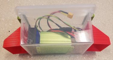
Since it's raining today, I decided to take the time to upgrade my MPT-7210A a bit. Put it in a soon-to-be weather resistance enclosure (waiting for the 3D printed vent/shrouds to finish, which I will attach to the 2 holes in the side of the box and seal with silicone sealant), and added a coax cable and external antenna to the ESP8266 (as well as adding some code which should allow it to reconnect if it drops connection), since so far I have not been able to successfully get data from my MPT-7210A except the very first day I installed it, and 2 days ago when I was fussing around with the panel location and reconnected the panel.


image_jutonn.jpg


image_oytvzi.jpg


Here is the data from 3/11 when it did work at least:


image_ojvulz.jpg
 
I have had one of these units for around 2 years. It was feeding a 24V (2x12V 110Ah) setup from 3 x 100W 18Vmp panels in parallel.

The thing would power up from the solar input (regardless of battery) first thing in the morning with the fan slowly accelerating as the voltage climbed - it ended up as a psudo alarm clock for me for a month....

The main issue I had was the tracking accuracy because it seemed to have issue with cloudy days when the output from the solar dropped faster than the internal software expects. This results in an over draw from the unit and it drops the output to zero as a result and then starts to build the output again.

As an extreme solution and experiment I wired up a pack of 10 x 500F supercapacitors (as a buffer to the inpout and through that this would then both prevent the cloud issue and help optimise the cloude edge peaks. The supercap pack would actually store around 4Wh of energy.

What ended up happening was the tracking pulled the voltage down to the minimum value (10-12V input) at times and then not allow the voltage back up, so my conclusion was that adding any additional capacitors on the input would potentially reduce the overall energy captured.

What was beneficial though )very very marginal) is that I could disconnect the solar when it was very low input and allow the capacitors to charge up enough to then allow this energy to go through the unit. Without them the unit would not power up properly or the fan would use the power. Again, this is so marginal that it would not even recover the cost of a single supercap.....

Other than that they are a good unit with a nice display.
 
completelycharged There is no tracking function built into it. Its manual and you need to set the power point voltage your self. If its not set properly the unit will walk all around the place.

So if you want a proper MPPT tracker then this unit is not the right one :)
 
daromer said:
completelycharged There is no tracking function built into it. Its manual and you need to set the power point voltage your self. If its not set properly the unit will walk all around the place.

So if you want a proper MPPT tracker then this unit is not the right one :)

There is some degree of tracking, look at the chart in the post by rev0 and the pattern of output through the day. Explain the circuit behaviour between 0 and 1hr for the W and V in the chart ? In the chart 1-2.25hrs is clear sun with a couple of clouds/interruptions - the profile of V and W outpout either side seems more like basic tracking to me.

I have tried setting the Vmp level and experimented a lot with the unit, the basic issue is the units seem to have a difficulty tracking quick output decrease from the solar, whcih a passive component device would never have.

If you set the Vmp way higher than your actual Vmp for the solar panels the unit will track close to the actual Vmp in bright sun.... or at least my unit does (and it is 2yr old so may have older firmware programming)... might be just my unit.
 
If I can get my logging working reliably (currently it seems to only work when powered by the USB port, doesn't like when the voltage of the charger slowly ramps up), I'll do some science with the Vmp settings to see what produces the highest output.
 
image_avizgp.jpg

Correction - 12s capacitor pack. Had to take one set of the resistors off - scavenged for a different project while away.
Had a balancer for them, but it was terrible because the (chinese sourced) capacitors have that much variation between them (tollerance around 30%).
The resistors were efective means of 24x7 bypass balancing for the caps - basic higher the V more I... and did not run them anwhere near the limit becauase of the poor quality of the caps.
 
Yes i know it does some kind of tracking and its useless :p I tested it for 2 hours and then i ditched it and only use it for smaller tests :)

The thing when setting it higher is that it drags down to what it can push through kind of. if you have a smaller panel like 20W it will behave very weird but if you have bigger panels it works better. Though not sure if its different from unit to unit but the units I have had none of them tracked even close. Comparing to any of my other devices none of them worked more then when full sun and when the point was set properly. Outside that they where atleast 20% below the others :D
 
Mike still seems to be liking his. It's definitely a great value if nothing else, $27 and it's still quite a step above a cheap PWM controller.

Anyhow, finished my mods, debugging the ESP8266 logger was a pain in the butt. Apparently, it does not reliably start when the voltage is slowly ramping up (like when the sun rises and the panel voltage slowly creeps high enough to turn the charge controller on). I had to add a power on reset circuit that holds the ESP module's reset line low until the input voltage exceeds ~10V. It's just an op amp that compares the 3.3V LDO voltage to the divided down internal 10.6Vbuck converter output. When the buck converter output is high enough, reset goes high and lets the ESP8266 boot up. At first I tried controlling a USB power enable switch, which would just switch 5V on when this same thing happened, but it was still unreliable. So far this seems to work, we'll see how it does in the real world.

Here's the simplified system schematic as it is today:


image_jyfqzt.jpg


And here's the final weatherproofed box, added a couple vents where the air will circulate and the wires will exit. Used silicone sealant around these 3d printed vents, hopefully this keeps the water out:


image_fmxuds.jpg
 
I think yehu came up with the best idea for these units: He has removed the front panel and added a big fan in their place cooling the whole unit from atop. He's placed the panel with the LCD screen alongside. You can see that in a couple of his videos, although he hasn't made one specifically for the MPT7210A unit.

I also believe these units are quite good for their price, give lots of control over the charging parameters and can be used as DC-DC boost converters reliably. However, a 100Wp panel is the minimum (says so in the chenglish manual), the tracker just doesn't work right under a smaller panel.

I would also appreciate it if it was a buck as well as a boost converter. This unit, being a boost converter, needs to be wired to at least an 8s battery, since most modern solar panels have an MPPT voltage of around 30V.
 
So I still can't figure out why the ESP8266 is not reliably starting up/connecting, so my inelegant solution is of course to use more batteries... I gave it a 4p pack of junk bin cells (6.81AH total) which should be enough to keep it alive for ~2 days with no sun recharging it. It's charged back up via a buck converter powered directly from the panel. Voltage on the buckis set to 4.2V output, but it's going through a schottky diode, so it is going to be around ~3.85V at 100mA load. I also added a reset button which can manually reset the ESP8266 if it's still not working.


image_hdvfhw.jpg
 
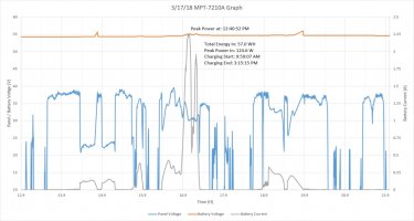
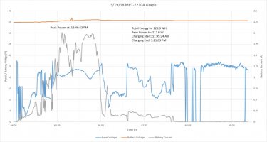
Now that logging is working consistently, here are a few captures:

3/17/18 - Overcast/mostly cloudy

image_jszqnp.jpg


3/18/18 - Sunny

image_gvnqlz.jpg


3/19/18 - Sunny

image_imdsel.jpg
 
Squiggles!!!!! :D
 
It would probably make more sense if you had somewhat depleted batteries, so as all available power would be moved by the charger from the panels to the batteries.
 
The chart for the 19th looks beter than my unit performs as the clouds in the morning ramp would have seen it drop and reset to zero once or twice. Overcast day looks typical basic track, pulling the V down to get the power out.

I really like these charts and data as it also shows just how much energy is available but not being used - incentive for larger battery or additional use of the power.... :)
 
Not sure what you mean by not being used, I've been waiting 3 weeks for my battery to get filled up! I can drain it in 45 minutes of charging my Nissan Leaf as I did a few weeks ago :p Otherwise I can use my pack to power other household loads for a much longer time, but I'm in an apartment so it's not a real powerwall setup and where my panel is I only get a couple hours of sun unlike a proper roof mounted system.
 
The data in the chart looks as if it should be charging a lot more than it is and as a guess you may have the upper voltage setting too low if your pack is not charging.... it would seem like it's charging up to a CV position and then backing off before the sun is lost...

Something does not look right in the data, for my unit at the end of day if it can pull power it pulls the panel voltage right down before the unit loses power completely. I would normally have 3 x 100W in parallel at 18Vmp going in and end of day it tracks down to 8-10V.

Your charts seem to be showing solar voltage up near Vmp and yet there is no output to the battery ?
 
completelycharged said:
The data in the chart looks as if it should be charging a lot more than it is and as a guess you may have the upper voltage setting too low if your pack is not charging.... it would seem like it's charging up to a CV position and then backing off before the sun is lost...

Something does not look right in the data, for my unit at the end of day if it can pull power it pulls the panel voltage right down before the unit loses power completely. I would normally have 3 x 100W in parallel at 18Vmp going in and end of day it tracks down to 8-10V.

Your charts seem to be showing solar voltage up near Vmp and yet there is no output to the battery ?

At those points the panel is partially shaded I believe, the open circuit voltage is high enough but as soon as it's loaded it drops significantly. It does look like there's some noise on the voltage, so i think the mpt7210a might be trying to ramp up but can't.
 
Hi there,

I am experiencing the same issue of MPT-720A controller shutting down every 5-7 minutes. I have connected a solar panel 120W, maximum power point voltage (Umpp) 27.6, open circuit voltage 32.2, IMPP 4.61 to a 48v lead acid battery (4x 12v batteries connected in series). Battery capacity is albeit very small 4.5ah. All 4x batteries connected in series show around 48v.

I have set the panel voltage to 27.6, battery voltage to 57, battery current to 4.5amp. After starting the controller, it keeps on ramping up the power from 20w to 75w, current from 0.45amp to 1.43amp, and voltage keeps dropping from 27.6 to around 22. Voltage then hovers around 22 and 21.9 and in few seconds the controller resets the current to zero. Controller starts up again in about 20 seconds and again ramps up to 75w. It keeps going in cycle.

I have tried setting the panel voltage to 30, 27.6, 27.4, 27, 26, 25, 24 to see if panel voltage setting is causing any issues, but the problem persists.

I was wondering if you were able to figure out a fix for this issue and share with me. I am in bay area, CA. Would be glad to do a quick phone call.

Greatly appreciate your help here!
 
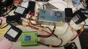
So like many people that purchase these I'm not really using them all as intended. I use it in conjunction with a 12v led power supply to charge 24v and 36v lithium packs for e bikes and off grid UPS kits. At this point I have 3 of these things and I have the same issue with all 3. I will set the amps to 9 or 10 then start charging my packs, but the charging amperage never goes above 3.5. I've tried different voltage settings, running many battery packs in parallel,as well as setting the battery amp hour and charge time to very low. I understand lowering the amperage as the batteries get fuller is good for the batteries, but why won't it give me more juice?
I purchased a 250W 12v led power supply to power this thing so I could get a fairly rapid charge (at least up to 80%) on my 16ah ebike battery bank, but now it takes 3 times longer than I had planned on.
The batteries for the ebike I'm charging are 25.9VDC 7 cell 20650 units with their own BMS and low voltage disconnect.
I've got the high charging voltage set to 28.8 in the MPT-7210A.
I've attached a photo of the setup and readout on the display.

image_rrybdp.jpg


Any advice would be greatly appreciated.
 
Back
Top