

You are using an out of date browser. It may not display this or other websites correctly.
You should upgrade or use an alternative browser.
You should upgrade or use an alternative browser.
New Powerwall in Romania
- Thread starter cat23
- Start date

The stats on the panels
(Pmax) : 280W
(Vmp): 31.83 V
[size=x-small](Imp): 8.76 A[/size]
[size=x-small][size=x-small](Voc): 38.85 V[/size][/size]
[size=x-small][size=x-small][size=x-small](Isc): 9.33 A[/size][/size][/size]
[size=x-small][size=x-small][size=x-small][size=x-small]60 cells(6 * 10) polycristaline[/size][/size][/size][/size]
So Batrium it is
I have those packs already built, but i have cells for another 14-15 60p packs, too busy (lazy) toassemble them. Probably the second set will be 80p and used in parallel with the first one.
I want to use AZ_tekkie s 3d printed mounts, so it is very flexible in this matter.
https://www.thingiverse.com/thing:2572115
(Pmax) : 280W
(Vmp): 31.83 V
[size=x-small](Imp): 8.76 A[/size]
[size=x-small][size=x-small](Voc): 38.85 V[/size][/size]
[size=x-small][size=x-small][size=x-small](Isc): 9.33 A[/size][/size][/size]
[size=x-small][size=x-small][size=x-small][size=x-small]60 cells(6 * 10) polycristaline[/size][/size][/size][/size]
Korishan said:cat23 said:I have two questions
1. The panels - I have in mind some 280W panels, but i am unsure about this max 80V MPPT - 105V max PV input. Sould I go with 2 panels in series or 3 (38,85V open circuit, 31,814 Vmp).
2. BMS - i want to use the Batrium, in the first months i'd rather not spend 500-600 eur on it. The packs are matched quite well, buit in 2018, harged, let to rest. After one year, the voltages are in .07 V range of each other. Is advisable to use them without Batrium this summer?
Welcome back
1) What are the other stats on the panels?
2) That's really nice to only have that small of a drift. At least you know you don't have any self dischargers. I would still recommend a BMS of some sort, even if a cheap one. But at least monitor voltages on a daily basis. Perhaps use those led volt meters on each pack to make that easier.
It's one thing for them to not drift while resting and back/forth current flow. It's another to start moving current around. You're making them work now so they may drift a little more.
So Batrium it is
daromer said:Welcome. Note that you need a decent size battery to start. To mnay start with to small battery and Wear Them out. Pip 5kw need atleast 14s120p to cope with the load properly. Ie design wise.
I have those packs already built, but i have cells for another 14-15 60p packs, too busy (lazy) toassemble them. Probably the second set will be 80p and used in parallel with the first one.
I want to use AZ_tekkie s 3d printed mounts, so it is very flexible in this matter.
https://www.thingiverse.com/thing:2572115
Seeing here that my last post was three years ago makes me pondering about procrastination
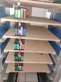
So, last November I finally put the system to work. The PIP-2424MSE1 is fed by 4 460w mono panels in 2s2p configuration (will ask an advice about this later). From November to late February, it charged a bank of 60p7s, then I replaced it with another 80p7s bank and this month I upgraded the 60p to 100p and added them as a second bank, giving me around 9kw of storage.
More work to be done in the layout of the inverter and fuse boxes and replacing the MDF trays with something less flammable, not to forget finishing the DYIBMS, based on Stuart Pittaway's project.
Now, I have a problem. The PIP doesn't want to charge over 20A, despite having a 40A MPPT.
In the manual it says that the total amps (40A) should be divided by the current provided by the panels (10,6A), giving me the number of panels in parallel. From what I understand, this is correct for the PWM charger, but not for MPPT, which is able to take a maximum of 20A (two in parallel) at 80-90V (two in series) from the panels and transforming that to 24-28V and 40A for the batteries.
I triple checked the menus, everything looks fine.
My last option is to put the panels in 4p configuration, but I don't really understand.
Attachments

Wolf
Moderator
- Joined
- Sep 25, 2018
- Messages
- 2,009
Quick Answer.
Your VOC voltage on your individual panels is ~49.5V with ~10A so 2s is going to give you ~100V at ~10A.
Your 2p2s configuration will give you ~20A. Just remember series connections give you higher voltage but the amps stay the same.
parallel connections the voltage stays the same but amperage increases.
Your PIP can handle up to 105V VOC so more 3 panels in series would give you 150V and that's too much.
Nevertheless the max Wattage you will get from your panels is 1840W divided by the100V coming from the panels is 18.4A
Unfortunately to max the PIP you would need a 2s4p or another 4 panels.
Wolf
I removed one 2S, leaving the setup as 2S, nothing changed, only the voltage dropped like 2V. The current coming from the panels was 7.8A, into the batteries going 20A dead, not 19, not 21, so it looks like a limit from the charger.
If the model was PWM, it would have make sense to go to 4P in order to boost the Amps to 40, but for MPPT I tend to belive is not the case, just because it managed to do 20A from a simple 2S, drawing only 7,8 from the panels.
I think the PIP is limiting somehow to 20A, will make a test next weekend with another inverter.
MarcoWasRight
New member
- Joined
- Jan 6, 2023
- Messages
- 1
Just curious did you ever do the fan mod to your Opus to speed up the process?
View: https://www.youtube.com/watch?v=Gfbm6nUxQns
Long story short the Opus fan isn't strong enough the heat created causes the cells to get hot and the charger to stop and start during discharge. This is where the "Opus tests 10% higher" thing came from
1. Cells will discharge a higher capacity between 35 and 40 Celsius than they would at room temp but that's going to degrade them faster over time.
2. The constant stop and start is allowing the voltage to rebound so its like starting the discharge again when the test is over because the cell rebounded to 3.4V and that's not the proper way to do a discharge test.
Now if you do all your testing on unmodded Opus chargers then they'll all roughly have the same amount of error but doing this mod just prolongs the life of your charger, stops your cells from getting heated during this one discharge and no more annoying Opus fan screeching. Just incase you still have more cells to test thought I'd throw this out there.
Yes, the older Opus (the one with the battery spill I wrote about couple of posts ago) has the mod already done, the newer one will follow soon.Just curious did you ever do the fan mod to your Opus to speed up the process?
Regarding the PIP 20A charging problem, looks like I was right suspecting that it was the problem and not the panels. Today, as a test. I replaced the PIP with a borrowed PNI SC1800 3kW inverter and "voila", 53 amps going into the battery banks with the same panel setup.
I will wait to see if the MPPSolar support team can offer a solution (firmware update maybe?).
Wolf
Moderator
- Joined
- Sep 25, 2018
- Messages
- 2,009
Ah that makes sense I was confusing input amps with output amps my error.53 amps going into the battery banks with the same panel setup.
Yes 1840W charging a 24 Volt system would theoretically give you 76A so at 53A you are pulling 1272W from the panels.
Perfect.
Wolf
So, for any other DIYer interested in PIP-2424MSE1, I received an email from MPPSolar saying that when the string voltage is over 70V, "to ensure the inverter operates at safety temperature", the MPPT limits itself to 20A.
I didn't see anything like this written in the manual, in the specifications or anywhere (I'll double check this weekend, just to be sure). It's kind of misleading selling 40A charging and 105V maximum panel voltage and delivering only 20A.
I didn't see anything like this written in the manual, in the specifications or anywhere (I'll double check this weekend, just to be sure). It's kind of misleading selling 40A charging and 105V maximum panel voltage and delivering only 20A.
hbpowerwall
Administrator
- Joined
- Oct 7, 2016
- Messages
- 2,219
makes sense, good to see they try to protect them selvesSo, for any other DIYer interested in PIP-2424MSE1, I received an email from MPPSolar saying that when the string voltage is over 70V, "to ensure the inverter operates at safety temperature", the MPPT limits itself to 20A.
I didn't see anything like this written in the manual, in the specifications or anywhere (I'll double check this weekend, just to be sure). It's kind of misleading selling 40A charging and 105V maximum panel voltage and delivering only 20A.
Yup, but I would have liked to be informed in advance about that, now I just ordered another invertermakes sense, good to see they try to protect them selves