Powerwall for Electrical Goodies

higher_wire

Member
Joined
Aug 30, 2017
Messages
61
I'm designing a powerwall setup for the eventual move to off-grid solar. I'm collecting 18650s, and planning to connect them similar to HBPowerwall (14s80p, ~10kWh), and expand as I continue to collect cells.

  • 48v system
  • Charge controller: MPP PCM60x
  • Inverter: TBD
  • BMS: Leaning toward TinyBMS(awaiting a response to my questions)
I would also like to be able tocharge a 48v electric bike and eventually an EV converted car, both of which will have 18650s in an 14sXXp configuration. That is, it would be nice to connect the bike'sbattery pack(s) to the powerwall orcontroller to charge, using connectors such as the APP PP75.As I understand, this will be doable in spite of differing capacities,as long as voltage capacity is the same.

I also plan to initiallysegregate the house so that all lights andsmall appliances running 110VAC will be able to run completely off-grid, with 220VAC (air conditioning, dryer, water heater, etc.) running on-grid in the short-term, due to a lack of cost-effective inverter options at the moment. My power company charges a monthly$50 "grid use" fee for on-grid solar, which is more than my average monthly bill (less taxes/fees), so I would like to keep it completely divorced to avoid this.

I'd appreciate any input on this proposed system.
 
So a full year later, and I actually have a working off-gridsolar setup for most of my electrical needs (air conditioning, stove, and clothes dryer notwithstanding). My current specs and equipment are listed below. This post will act as a quick reference and table of contents as things change. Be on the lookout for a system schematic and more photos.

Note that I'm still cleaning up the wiring

  • Powerwall Specs: 51.8v nominal, 166Ah capacity, 8.614 kWh

    image_iikygg.jpgimage_wmmynv.jpg
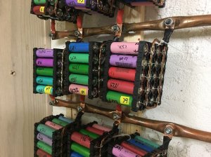
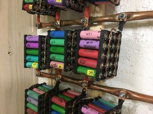
  • Powerwall Configuration:14s/80p(effectively 48v)
    -1120 cells @2078 mAh average/cell
    -Modular so cells can be added in 20p (40Ah)blocks
    -I took inspiration from owitte's modular powerwall
    -Connections are5/8" copper HVAC tubing with PEX wall holders
    -20p blocks use 2 strands of12 AWG copper wire, with 28awgfuse wire on positive and 20awg negative
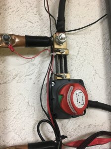
    -I'm usingthis battery disconnecton the battery negative
  • Solar Panels: qty 40 165w Solar Frontier SF165SCIGS panels (datasheet)
  • Charge Controller: qty 2Sunnysky 60a MPPT
    -One controller for my rooftop array (24 panels)
    -One controller for my garagetop array (16 panels)
    -These allow you to set battery type, charge current,charge andvoltage
    -It comes with two flimsy L brackets, and hangs awkwardly on my stucco wall. But I haven't had any issues otherwise.

    image_bnhdza.jpg


    image_jusywm.jpg
  • Inverter: Sigineer 6000w 48v, 240v split-phase (USA)

    image_dvjmor.jpg
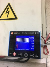
  • BMS: Chargery BMS24T
    -The BMS controls charge and load via two Albright 200a SU-80 contactors, andclaims a1.2a balance function. It seems to be keeping the cells within ~50mA fairly well.
    -The BMS monitors SOC% using a 600a shunt on battery negative. I connected mine directly to thebattery disconnect switch.
  • Misc:
    -My panels came with a Hiasa enclosure. It included DIN rails, to which I was able to mount my breakers andancillary equipment
    -Mysolar(2P)and charge(1P)breakers
    -MyANL battery fuse, connected to battery positive
    -Here's myground junction
    -I used these DIN mounts for my contactors, fuse holder,ground junction, converter and fan control
    -Because Phoenix gets stupid hot in the summer, I wireda 12v buck converter and cooling fan control
    -The enclosure also came with an ABB INCA emergency stop button, which I wired to cutoff the contactors in case of emergency.
    -The inverter AC output is connected to the house via this Reliance 50a transfer switch
 
Thanks! I went back and forth between this and the HB style, but ultimately chose this for the ability to add capacity. I think I'll try the more compact shelf style like I've seen others use if/when I change things around (aka move to a bigger place).

Here are a few more shots. The BMS24 is up and running, and seems to be balancing things nicely. It unfortunately does not have a way to log information, nor do the charge controllers (they have RS485 ports, but the seller has said that they currently don't support logging). Being developed for electric transport rather than solar powerwall applications, functionality is limited compared to Batrium; but what can you expect at half the price.

The BMS has a warning LED and buzzer for if/when things go awry. I have the LED connected for quick reference, but not the buzzer. The BMS is designed to light the LED andcut load and/or charge whenever there's a fault.


image_vocsoq.jpg


image_qjgzds.jpg


image_czihaw.jpg


image_zdoxrx.jpg


image_wnyeru.jpg
 
hookemdevils22 said:
So a full year later, and I actually have a working off-gridsolar setup for most of my electrical needs (air conditioning, stove, and clothes dryer notwithstanding). My current specs and equipment are listed below. This post will act as a quick reference and table of contents as things change. Be on the lookout for a system schematic and more photos.

Note that I'm still cleaning up the wiring

  • Powerwall Specs: 51.8v nominal, 166Ah capacity, 8.614 kWh

    image_iikygg.jpgimage_wmmynv.jpg
  • Powerwall Configuration:14s/80p(effectively 48v)
    -1120 cells @2078 mAh average/cell
    -Modular so cells can be added in 20p (40Ah)blocks
    -I took inspiration from owitte's modular powerwall
    -Connections are5/8" copper HVAC tubing with PEX wall holders
    -20p blocks use 2 strands of12 AWG copper wire, with 28awgfuse wire on positive and 20awg negative
    -I'm usingthis battery disconnecton the battery negative
  • Solar Panels: qty 40 165w Solar Frontier SF165SCIGS panels (datasheet)
  • Charge Controller: qty 2Sunnysky 60a MPPT
    -One controller for my rooftop array (24 panels)
    -One controller for my garagetop array (16 panels)
    -These allow you to set battery type, charge current,charge andvoltage
    -It comes with two flimsy L brackets, and hangs awkwardly on my stucco wall. But I haven't had any issues otherwise.

    image_bnhdza.jpg


    image_jusywm.jpg
  • Inverter: Sigineer 6000w 48v, 240v split-phase (USA)

    image_dvjmor.jpg
  • BMS: Chargery BMS24T
    -The BMS controls charge and load via two Albright 200a SU-80 contactors, andclaims a1.2a balance function. It seems to be keeping the cells within ~50mA fairly well.
    -The BMS monitors SOC% using a 600a shunt on battery negative. I connected mine directly to thebattery disconnect switch.
  • Misc:
    -My panels came with a Hiasa enclosure. It included DIN rails, to which I was able to mount my breakers andancillary equipment
    -Mysolar(2P)and charge(1P)breakers
    -MyANL battery fuse, connected to battery positive
    -Here's myground junction
    -I used these DIN mounts for my contactors, fuse holder,ground junction, converter and fan control
    -Because Phoenix gets stupid hot in the summer, I wireda 12v buck converter and cooling fan control
    -The enclosure also came with an ABB INCA emergency stop button, which I wired to cutoff the contactors in case of emergency.
    -The inverter AC output is connected to the house via this Reliance 50a transfer switch
very nice setup, but your wall is way too small! :D

Have sun!
Oliver
 
Nice work!
 
very nice setup, but your wall is way too small!

Indeed it is! I have 7 more packs assembled, and picking up more cells soon. It gets me through the night as it is, but SOC hits about 5% at avoltage of ~48 by the time I check in the morning. I would have another full set of 14 packs, but I tried to run it with 14x1 packs without a proper BMS and ran a few flat. :-/
 
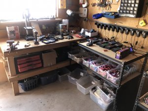
Update! I moved to a new housewith a 200 sq.ft (18.5 sq.m) detached garage in the back yard. I've fitted 12 of my 165w panels to the flat roof and transferred all of my power conditioning equipment and batteries. I've dubbed this the scorpion shack because it was pretty derelict when I first moved in, and I've had a few run-ins. ButI now have a nice little off-grid spot to build my batteries and take care of other projects. I am working to outfit my house with the rest of the panels.

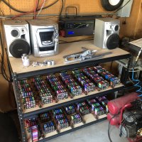
I reconfigured my powerwall so it's now a powershelf. The plan is to stack packs vertically when I exceed the 6 pack depth limit.


image_zvmtni.jpg


image_rknfka.jpg


image_zdufiv.jpg


image_jtllqr.jpg


image_kipxqq.jpg
 
Nice.
 
Very Cool! and I too have a working system that I hope to expand to power most of my house. Its a lot of FUN!

I also made the decision to avoid power company requirements - so my system is also off-grid.

I run the output of the Inverterinto a sub-panel (seen in myprofile picture)andthen distribute power to various places.

1) Destination 1:[size=small]A 240v@50amp circuit is run from the main panelAND a 240v@50amp circuit is run from theinverter to the automatic transfer switch (box at bottom of picture). The output of the automatic transfer switch feeds the Pro-Tran manual transfer switch - which is wired into main panel.[/size]
[size=small]image_jftekv.jpg[/size]
The manual transfer switch gives individual circuitcontrol because GEN position will get power from theautomatic transfer switchandLINE position will get power from main panel as it originally did.

2) Destination 2: A set of 30amp Go-Power automatic transfer switches power a set of 3000 wattAPC UPSs. I ran sockets to key computer/tv areas in house that are powered from the output of the APC UPS. The 30amp Go-Powers get shore power from main panel and generator power from Inverter distribution box.This takes care ofsensitive equipment that can't take the automatic power switch that occurs twice a day.

image_npcmbw.jpg


All of this lets me
1) Shut the PV/off-grid system off to work on it without any disruption to the house power.
2) Consume all the PV/off-grid power... and let grid take over automatically if the PV power is not enough for 24hrs for that day. This let's me maximize my ROI and of course in an grid-downemergency I could use less power so it never shuts off.
 
@OffGrid, is that manual transfer switch a Reliance Pro 510C? I have one that I used in my last build, and am debating whether I will install it for the house or build a completely separate system. The former would require me to move my power conditioning equipment to the house, while the latter would require another inverter and battery pack (I have an extra charge controller).
 
hookemdevils22 said:
@OffGrid, is that manual transfer switch a Reliance Pro 510C? I have one that I used in my last build, and am debating whether I will install it for the house or build a completely separate system. The former would require me to move my power conditioning equipment to the house, while the latter would require another inverter and battery pack (I have an extra charge controller).

I bought "Reliance 50 Amp 10-Circuit Manual Transfer Switch" from Home Depot that you see in the picture:
https://www.homedepot.com/p/Relianc...ircuit-Manual-Transfer-Switch-A510C/206503336

But yes - I believe its thePro/Tran 2 - 50amp - A510C

NOTE: I performed the'wire upgrade' described by youtube @LithiumSolar
- as I agreed with his analysis that the wiring seemed diceyfor afull 50amps :)
 
Some updates. First, I am in the process of installing the remaining 6kW of panels on my home. I'm moving my equipment into the shop attached to my garage in order to reduce wiring: it's about 125'/40m from my main panel to the shop, so it's easier/cheaper to centralize equipment and just run a couple wires for the 2kW panels on top of the shop. However, my modular power shelf isn't space-friendly, which was going to take some serious work to move until...

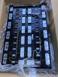
I found some new goodies today at the local e-cycler. Three Samsung ESS boxes, 7.6kWh each (81v/94Ah). Brand new in the box, returned due to "bad tray." I can't find any info on them, but it appears that there were COM device(s) and fan(s) that have been removed. Looks like they have these 350Wh cells in a 22s1p config. The voltage is too high for my needs, so I plan to tear into them and reconfigure to a 14s4p config.

It looks like the cell connections are the metal strips shownin the second pic, with those two wiring harnesses being for a BMS.


image_pmqicz.jpg


image_xhvghx.jpg


image_gqocce.jpg


I also added a few morecells since my last update. I now have 1400 cells and10.7 kWh. Here's a snapshot of the Excel file I use to track it.

image_lnfqpv.jpg
 
Looks like there are a couple cells that dropped down below 2v. I havent done a full voltage check on all yet, but overall voltage is low on each. The one I checked had cell 22 at 1.48v, all others at 2.95-3.05v. It looks like the individual cell connections are welded to the batteries despite them having threaded bosses. Itll be a pain to remove if thats the case.
 
higher_wire said:
Looks like there are a couple cells that dropped down below 2v. I havent done a full voltage check on all yet, but overall voltage is low on each. The one I checked had cell 22 at 1.48v, all others at 2.95-3.05v. It looks like the individual cell connections are welded to the batteries despite them having threaded bosses. Itll be a pain to remove if thats the case.


Easy fix... you can just connect a 1s charger and bring up the low cell only.

i would also leave it assembled... Im sure there is something else you can do with it. Lots of value in leaving it as it is.
 
Here is a picture of the Samsung module with the BMS board still installed. The markup shows how you could turn two of these modules into three 14S 48V packs.
 

Attachments

  • unnamed.jpg
    unnamed.jpg
    140.6 KB · Views: 136
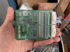
Here is the BMS board itself
 

Attachments

  • FC554F13-63E4-4422-BD08-610807F3A39B.jpeg
    FC554F13-63E4-4422-BD08-610807F3A39B.jpeg
    3 MB · Views: 124
  • A76BC5FD-93C5-48AE-8116-279C3D2F8F89.jpeg
    A76BC5FD-93C5-48AE-8116-279C3D2F8F89.jpeg
    3.1 MB · Views: 125
  • 96932B98-C115-4F98-9EA4-5004118AE5B8.jpeg
    96932B98-C115-4F98-9EA4-5004118AE5B8.jpeg
    2.5 MB · Views: 130
  • F1AE6427-32B9-473B-8225-7D1384BCC37B.jpeg
    F1AE6427-32B9-473B-8225-7D1384BCC37B.jpeg
    2.8 MB · Views: 137
Back
Top