Question ... Dual Coil Limiter cable for GTIL

507PowerWall

Member
Joined
Jun 6, 2020
Messages
103
Hi All,

I just ordered a two CT clamps rated 100A / 50mah ...
... to connect them in series to cover both hots..... and suppously this will allow us to read properly the whole house consumption.....

But I was checking this guy dual ct clamp "Calibrated" and "Adjustable":

no afialiated link:
Here

Here's the adjuster:
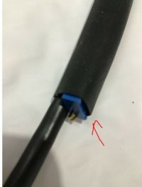

image_fticvv.jpg


Question, I was planing to get cts and test load and reading at home ... but in my noob environment just doing the series connection will not be calibrated and probable will not read load right... I know will not be perfect reading but a 0.5% deviation will be ok?

The cable comes with :

"The limiter cable is a special 2 coil electronically calibrated cable with a circuit to always allowapproximately7 watts down, and TWO coils to monitor the standard unbalanced load."

newbies should go for the cali and adj dual CT ?

I'm planing to test by myself and if I cant make it... do the other route....

I leave it here just in case other noobs are planing the same....

and would like to here ur experiences and input about dual CT

CG.
 
I am going to guess what you need to do to test and calibrate the CTs is to put a known load and see what the inverter says. Then make the adjustments with the trim pot to fine tune it.

I can't tell what model of the SCT sensor those are to look up their specs. They made by YHDC. I have several of them and also built a power monitor system for my mains. Altho mine doesn't interface with an inverter.
He's definitely charging a premium for those cables/sensors. The sensors alone are <$10 a piece, depending on the amp rating needed. The connection that goes into the inverter looks to be a standard cable as well. The only difference I can see here is he added a trim pot inline to allow for fine adjustment of the sensor.
 
Korishan said:
I am going to guess what you need to do to test and calibrate the CTs is to put a known load and see what the inverter says. Then make the adjustments with the trim pot to fine tune it.

I can't tell what model of the SCT sensor those are to look up their specs. They made by YHDC. I have several of them and also built a power monitor system for my mains. Altho mine doesn't interface with an inverter.
He's definitely charging a premium for those cables/sensors. The sensors alone are <$10 a piece, depending on the amp rating needed. The connection that goes into the inverter looks to be a standard cable as well. The only difference I can see here is he added a trim pot inline to allow for fine adjustment of the sensor.

Yes is aYHDC 100A/50ma
And I will test first my series attempt... get some help and then ... last resource... sink few bucks for that cable...
 
I own-use 2 of the 2kw gtil2s. Ive used 2 different types of CTs. The cables he sells do work, although expensive.. he calibrates the CTs with an inline resistor, just recently he started adding a trim pot due to variations from one inverter to another.. I made a set of cables and did not use a resistor and they worked well. I have an iotawatt that confirmed this.. my CTs were to small for my wires so I ordered a cable from him with bigger CTs but I have the trim pot adjusted so that it might aswell not even be in the wiring.. if u are using the 1kw inverter (thats what the seller owns) then Id recommend the inline resistor. the trim pot is for fine tuning.
Whatever u decide to do Id make sure to have a really good solar-home energy monitor to confirm it was working properly..
 
aleks2a said:
Hi All, just made this cable myself, sensors connected in parallel in my case (one sensor reversed).
Recorded all details here:

Excellent contribution champ.... is each one test the best performance from options at hand!

CG.
 
CTs In parallel or series will allow the inverter to produce till grid gets down to 0-10w. Im fairly certain the clamps are supposed to be in series tho. Cables from Art Lowery (has sold 1000 ct cables for 240v splitphase supply) are combined in series. Several of us have taken them apart to confirm that is how they are made. Way I see it, The CTs sense the amps and then send an appropriate voltage signal to the inverter. Amps amount is not sent to the inverter. The CTs in series allows that voltage signal to be combined that each ct (on each main) is sending to the inverters. Legs are most of the time not balanced, wiring in series allows the uneven voltage signals (due to different load amounts on each leg) to be combined, therefore letting the inverters supply all the homes load. When in parallel the volt signal from one ct is dropped to the volts of the lowest ct. therefore not allowing inverters to produce for all of the loads. I really good monitor like an iotawatt is needed to see if ct sensing cables are working correctly. Even if they are wired in series.
In parallel the inverter will probably also limit correctly even though both voltage signals are not getting combined. The inverter will still produce as much power needed to get the grid down to 0-10w. So if one leg is using 50w and other 200w then the inverter would only get a voltage signal equaling 100w (50w from each sensor) but like I said the inverter will continue to supply till 0-10w is reached I think.

On another note Id like to throw out there that if anyone has 2 CTs (instead of 1) in their utility meter then they should not supply 240v from a GTIL2
 
Partly correct, partly wrong.

There are CTs with internal "burden resistor" that output voltage. These will have markings like "100A : 1V", meaning 50A flowing through the hole will result in a 1V output. These have to be connected in series to sum up the output voltages.

CT's without an internal burden resistor will output current. These will have markings like "100A : 50mA", meaning 100A flowing through the hole will results in a 50mA output. These have to be connected in parallel to sum up the output currents.
Usually a "Varistor" is still built in to dissipate potentially dangerously high voltages, but they're not active under normal use.

My GTIL(1kW, 22V~65V) had the 2nd variety without an internal burden resistor, so I connected my 2 CTs in parallel, and it's working perfectly.
 
My CTs are the same as yours. 100amp 50ma (mine are 60ma). Mine are wired together in series. My system is working correctly and not backfeeding or underfeeding at all during any conditions. I have Iotawatt and Ive looked at every couple sec of many days. I also have the second version 5.1 inverter


Right its a 50ma output but still at a certain voltage which is what the inverter reads. The inverter doesnt read mA. Or am I wrong


Im thinking the version 5.1 GTIL2s have a resistor inside them that acts like a shunt to read the voltage signal and that voltage is what it uses to limit.
 
Yes, usually there is a burden resistor somewhere in the system to convert the current signal to a voltage signal. Since it's not integrated in the CT, it must be somewhere inside the GTIL.

Perhaps somebody can put a scope on the different CT configurations to figure out exactly what's going on, and how and when the GTIL reacts to the changes? I can't be bothered to do that...
 
Without testing it, it would make sense to series the CTs to combine the voltage signal from both legs since they are different voltages. Parallel wouldnt allow the different voltages to be combined. Parallel would allow the milliamperes to be combined, but Id assume the problem with that is that the inverter-limiter is supposed to receive mA up to 50mA. Thats why a 50ma clamp is used. Series will not allow the mA to be over the rated mA of one ct, while still reading the combined voltage (what the inverter uses to limit) from both CTs inside the inverter at the resistor.
 
Looking at this myself & i dont think its that easy to just serial/parallel reliably.
I'm assuming you're talking 120v split phase with 180deg out of phase? So if you had exactly 1000W on each phase in use, if you joined the CT's you could just be cancelling the phases out, showing zero power - when in fact you're balanced. The chance of this happening is next to impossible - which is why in practice its kind of working in situations.

I've got 3-phase 240v here, so i'll need 3 CT's.
To add the current without cancelling/interfering it might require a conversion to DC first, then parallel. So if either leg has current it will show up, and could be cancelled by another leg.

Thoughts?
Did i make sense?
 
I'm assuming you're talking 120v split phase with 180deg out of phase? So if you had exactly 1000W on each phase in use, if you joined the CT's you could just be cancelling the phases out, showing zero power - when in fact you're balanced. The chance of this happening is next to impossible

Yes, talking about 120v split phase system.
This simple adding only works when the live lines are in phase, definitely not with 3-phase. Works with split phase (180deg out), because the CT clamp on the 2nd phase can be flipped, making the outputs of the 2 CTs match phase.

Of course, there's a 75% chance to initially put one or both clamp(s) on the wrong way and have weird cancelling effects. Just flip and reattach the wrong CT clamp(s), and they will add up perfectly.
 
Yes, talking about 120v split phase system.
This simple adding only works when the live lines are in phase, definitely not with 3-phase. Works with split phase (180deg out), because the CT clamp on the 2nd phase can be flipped, making the outputs of the 2 CTs match phase.
So simple & elegant!!!
Easy with 2 phase & 180degree... love it
(wasnt sure what the US was running with their 240v)
 
Back
Top