Reviving an undercharged BYD 11kWh pack

Dala

Member
Joined
Feb 16, 2018
Messages
349
Hi forum!
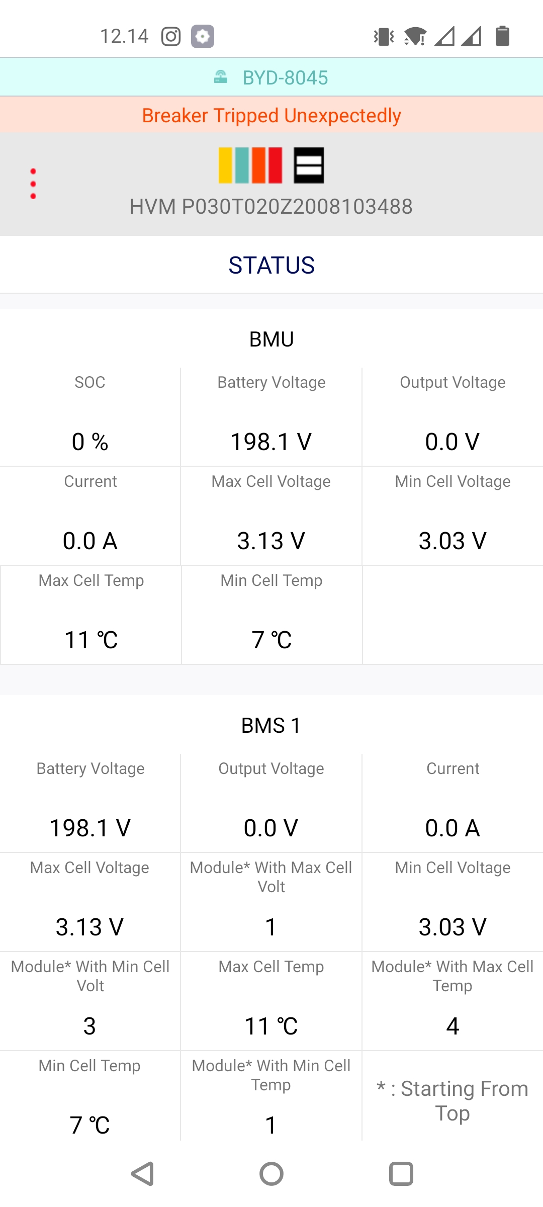
So I am in the middle of reviving a "broken" BYD 11kWh battery pack, that will be used with a Fronius Solar inverter.

Backstory, the pack was left at 0%SOC at -25C and not really wanting to work after that, tripping main breaker. So I dismantled the pack and most cells range between 2.6V and 2.9V. This to me looks like a possible undervoltage situation, which trips the BMS to not undercharge the cells further. Normally they shouldn't be discharged to 2.6V AFAIK?

bCJOR7L.png


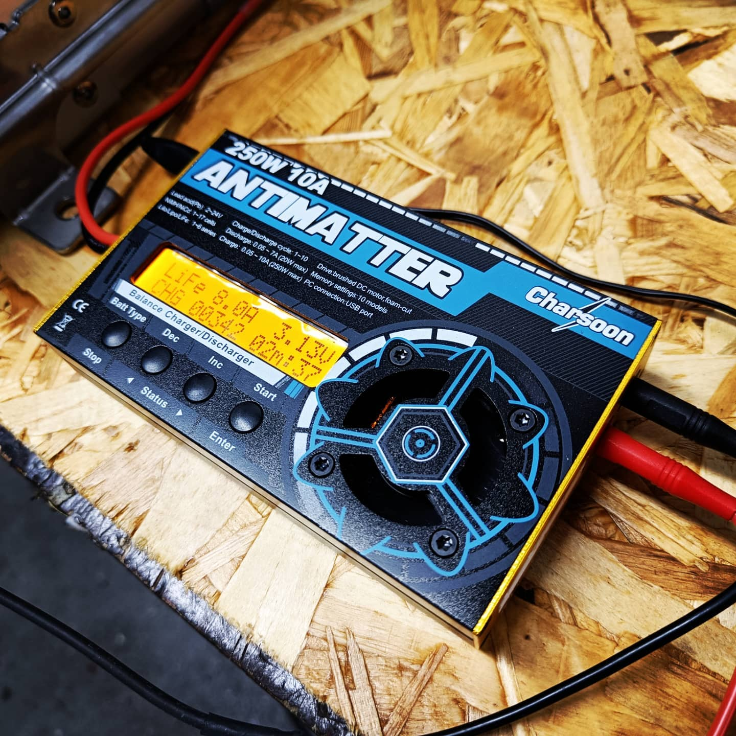
So now I'm charging up the cells individually before attempting to restart the battery. I set my LiPo charger to 3.3V programme to save time. Due to the flat nature of the LiFePo4 chemistry, will this be OK, or should I go for higher voltage? Really new on this chemistry, been mostly using LMO. Any tips at all appreciated :)

oaEo80V.png
 
Good link! I still need to go thru the other half of the battery to see if there's any cells that are lower than 2.6V, I really want to bring it up to a normal SOC% range, since these packs are not meant to go below 7%SOC (and that 2.6V is way below that already). But now just worried that a target of 3.3V with a LiPo charger might make it unbalanced :cautious:
 
You could try to disconnect them temporarly, wire them up in parallel and charge all at once with a max voltage of 3.3v
 
Hey Dala

would be nice if you could poste some more pics of the packs & BMS and also which battery it is exactly.
I gues it is a High voltage version with 4 modules?

I have just access to one number for now. If you would like to have some more, I can ask for a chargecurve with SOC numbers from a friend.
the lowest possible voltage is 3,03V, this is at 5% SOC.

Therefore I would suggest to charge them all only up to 3,1V and see what happens. charge them higher will probably confuse the BMS to much, because there is electricity which didnt came threw the current sensing ciruite.

wish you luck!
 
Hi @PAF , yes it is the BYD HVM 11.0 , so 4 big modules. Great suggestion with the charging, byt my LIPO charger only goes to 3.3V min :/ Looks like I need to hunt for another charger...

I will ofcourse take more pictures of it, and try to reverse engineer the RS485 communication so I can hookup 50kWh of LEAF batteries instead of these overpriced BYD packs!
 
it looks like the module on your Pic consists 8 cells.
6 LiIon cells are 25.2V, 8 LiFePo4 Cells @3,1V is 24,8V.
this would be a nice fit for your Antimatter and speeds up the charging dramaticaly if you could connect it propperly
 
They have to sell batteries over time, so killing them faster is the way to go.
 
According to https://cdn.shopify.com/s/files/1/0...ATTERY-BOX-PREMIUM-HVS-HVM-datasheet.pdf?1644
View attachment 26649
204v nominal so each module must be 51v nominal which would be 16s. Voltage range for each cell 2.5v-3.75v, 3.75v seems a bit high
later floyd
min Voltage is 3.03V @ 5% SOC
max Voltage is 3.65V @ 100 SOC
from our testing

maybee the marketing department wanted „round“ numbers and we got therefore 160 & 240V
or they just copied the numbers from the datasheet?
 
Last edited:
maybee the marketing department wanted „round“ numbers and we got therefore 160 & 240V
or they just copied the numbers from the datasheet?
Marketing departments often stretch the truth. My experience with LiFePO4 cells is 3v-3.38v is ~90% of original capacity, Of course all of my cells are used when I got them. I charge the cells to 3.65v wait until they have settled then test them.
3.03v x16 =48.4v 3.65vx16 = 58.4v so 4 modules would be 233.6v-193.92v. ? To make the cells last longer I would only charge to 3.4v~3.45v
Others in here are more knowledgeable than I am.
Later floyd
 
  • Like
Reactions: PAF
Lowest cell was 2.5V, highest 3.0V

I charged all cells up to 3.1V. I made a video on the pack:
View: https://www.youtube.com/watch?v=dKlKllykYCw


Now, it still doesn't turn on. SOC% shows as 0% in the app.
qiCBTR7.jpg


Any ideas on what to try next? I will try to get Modbus going so I can read the fault registers. The application just says "Breaker tripped unexpectedly".
 
Off the cuff....
Is 3.1v/cell high enough? Is there some kind of reset you can do? Is some kind of re-initialization needed since it went 0% SoC?
 
I agree probably too low voltage. I would charge the battery probably at least 3.2v per cell . Is the breaker a shunt trip breaker?
later floyd
 
1641727395305.png

This is the sunspec modbus protocol, register 803. It contains all the fault signals that the battery sends, so with this info I should be able to manually decipher what error bits are active. One of these is UNDER_SOC alarms, so let's see if any of those are triggered.

But yeah, I boosted some cells from 2.5V -> 3.1V, my gut feeling with LFP says that the system should be able to cope with the voltage as is now. Since the spec supposedly allows them to go down quite low. Let's see :)
 
Is there a way to tell the BMS SoC is now eg 50%?
Maybe put some current through the shunt so it registers rising SoC?
 
While I was connecting the modbus cables yesterday, I noticed the LED on the side is blinking in a pattern. I read the manual, and supposedly the BMU has this issue:
WFcwvJX.png


So, thinking about opening it up and inspecting the precharge circuit...
 
Very interesting project!

I see that you have a Fronius Gen24 Hybrid inverter. Do you know if its possible to activate the battery output\input of this inverter, without using a Fronius approved battery connected(fex BYD)?

I'm really wanting the Fronius Gen24 Symo Hybrid 10kw inverter, but seems there is per today no way of getting this to work with a DIY batterypack. Seems Solis inverters can do this with a DIY battery with a BMS, emulating Pylontech protocol over canbus.
 
Back
Top