Second Life Solar Car Battery

Peterator

New member
Joined
Jun 27, 2021
Messages
22
Hi all. I wanted to post about a project I'm starting, and it's got a neat bit of personal history to it.
Eight years ago, when I was in college, I helped build a battery pack for our school's entry in the 2013 World Solar Challenge. We designed the pack from scratch, built a custom BMS for it, the works.

Then, when the race was over, the battery sat collecting dust in a shop somewhere. I graduated and move on to other interests. Then I heard they were looking for a home for the battery, and I started learning about the second life battery scene, made an inquiry, and a few days later drove home with 8 kWh of ambition.

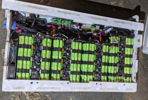
Here's how the battery looked when I got it:
Battery1.jpg

The pack is 13 17s39p. The original car had two of these wired in series. The BMS is still partially wired in, but to my surprise, none of the cells had been drained after 8 years of storage. Cells are Panasonic NCR18650B with maybe a dozen cycles on them, all at 3.55V except one at 3.45V.
The plan: I'll remove all the electronics (I don't trust anything I designed in college) and all the modules (groups of parallel cells - is module the right term?). I thought of reusing the box but it's too tight and I don't like how the modules are stacked. Wall-mount the modules, add a new BMS, connect to the solar/charge controller I already have, and use it to charge my Leaf.

There are a few decisions I'm still unsure about and would appreciate comments on:

Should I add cell-level fusing? Right now cells are connected with a pretty wide nickle strip (I'll get a pic once I get the modules out). My thought was to cut all the positive strips, let it sit for a while to make sure no cells are self-discharging (probably a redudant test considering everything still has charge), then solder a thin wire between the positive and the rest of the nickle. I don't plan to draw more than 1A per cell and I'd rest easier with the extra protection.

I'm also trying to choose a BMS. I like what I've seen from Batrium but it's just too expensive for me. The diyBMS looks neat but I worry about how much of a time sink it'd be to build and set that up. Daly is nice and cheap but I can't tell if it will do everything I want it to.

Last thing is the output. I don't want to muck with grid connections and regulations right now so I thought I'd use the pack to power my biggest load: My '17 Nissan Leaf. I use around 4-5 kWh each weekday for my commute. I figure I can just go battery->inverter->EVSE->car but I'm curious if anyone's gotten more clever then that.
 
Last edited:
I would suggest making another module "bank" of cells to make the battery 14s there is more usable voltage range with 14s compared to 13s. And also see if a dc to dc charger could be made for charging.

Later floyd
 
Love the back story. Look at all those fans! At 39p, you could go with 'lessor' BMSs than Batrium. Maybe Daly. At this point (8 yrs) you might well want to just take the cells out, retest, and build a new battery from them - including cell level fusing. Agree with @floydR that at 14s you'd find a much wider range of supporting equipment.

How do you plan to charge it? / use it? - via Solar Panels? As far as using it without getting into Power Company space - charging your car makes sense but you can also integrate it with general circuits in your home via ATSs or Limiters. If Solar Panels then these all-in-ones / off-grid units such as MPP Solar PIP or Growatt are very handy these days :)
 
Thanks for the tips. The (40W!) battery fans are super overkill - in the previous solar car race they couldn't charge the car at one point because of overheating and we weren't about to let that happen again!

So the charging situation is a little unique. My solar panels have integrated boost converters set to a constant power / constant voltage of 56V. The company that makes them is out of business and therefore I don't have access to the tools to change that voltage setting. With 13s max voltage is 54.6 - a little low, and with 14s I get 58.8 so it won't charge all the way. I thought I'd start with 13s and a cutoff or regulator to keep it from overcharging - but maybe it's worth building #14 and live with only getting to 4.0 V. I have some extra cells from the original build that should match these pretty well if I go that route.
I was curious if a dc/dc could be used to charge an EV. I don't see why not, but I've never heard of it done before. I also do want to integrate it into my home circuits - in my mind the EV charging is easier to start with but I might change my mind when I get to that point.

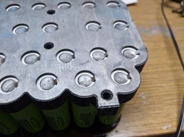
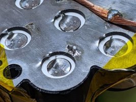
Anyway, I gutted the electronics and I just got the first modules out and took a couple pictures up close. The cell holders are 3-D printed, and the cells are a tight fit with extra spacing for air flow. The indents from the battery welds looked a little shallow to me, but I tested a few and I couldn't pry them off without severely deforming the nickel.
battery3.jpgbattery2.jpg
 
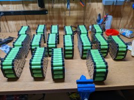
Quick update, all the modules are out now and sitting on my bench. Getting them out was easier than I expected, I just had to undo a few nuts and pull the retaining rods out of the stacks. I was careful to avoid shorts while taking everything apart, almost to the point of paranoia. The retaining rods in particular made me nervous because they're metal and thread through several module brackets.

battery4.jpg

I think I'll go ahead with my plan of replacing the positive connections with fuse wire, so I'll need to find the proper wire and test the soldering procedure before I do it 500 times. Clip the positive nickel, let it sit, check voltages, solder the wires, then add bus bars.
I also ordered a simple Daly BMS. Might upgrade later but it'll get me running.
 
I'm testing out the changes I want to make to the modules. I ordered some fuse wire (stuff is hard to find!), but it'll take a few weeks to get here so I wanted to work with what I have in the meantime. I found some thin wire with super thin strands, and my testing found they break at after a few seconds at 3.5A, and pretty much instantly at 5A. My pack should peak at about 1.0A per cell, and the cells are rated to 6A discharge so I feel pretty safe with this. Still the break current is pretty low so I should inspect them regularly.

I clipped the nickel on all the positive leads and tried soldering a wire in, attching it to the clipped tag to reduce soldering heat hitting the cell.
battery6s.jpg

I then tried soldering in a bus bar, and that didn't seem too tough. The nickel takes up solder quite easily. I think the 14 gauge wire I used is going to be too small, so I'll have to find some 12 or 10 gauge, which doubled up should take my 40A peak.
battery5.jpg
I learned recently I can get a limited grid-sync inverter GTIL for pretty cheap, so I'm rethinking my power output. I figure I can set it up so I never export power to the grid, plug it in, and I'm good to go? I'll need to do more research.
 
Fun to see your progress! If you're having trouble with 'fuse wire', just FYII use 30awg tinned ( https://www.amazon.com/gp/product/B01M0AXONC/ref=ppx_yo_dt_b_search_asin_title?ie=UTF8&psc=1 ) - its burns thru around 15a.

Remember that you're not fusing to protect individual cells - but rather to protect the overall pack if a cell shorts due to failure. So yes - you want the fuse wire to handle max charge/discharge per cell, but burn thru just has to be quick for as the other 38 cells try to short thru the bad 39th cell (if I counted correctly).

One side affect of cell level fusing is that it helps protect cells in the pack if you 'dead-shorting' a pack's main + and -. @hbpowerwall did some youtubes on this. Here's one of them -
- and if you look at youtubes next to this 'in time' you'll some others where he digs down on this. *I put my main + and - at opposite ends and sides of my packs and have had no trouble :)

I learned recently I can get a limited grid-sync inverter GTIL for pretty cheap, so I'm rethinking my power output. I figure I can set it up so I never export power to the grid, plug it in, and I'm good to go? I'll need to do more research.
Yes some folks do this thru devices such as this - https://www.amazon.com/ECO-WORTHY-1000W-Inverter-Limiter-System/dp/B095C6FTP6/ref=sr_1_2_sspa It should have anti-islanding so it won't work if the grid goes down (https://www.solarmarket.com.au/blog/anti-islanding-protection-for-grid-tie-solar-power-systems ) - so you need a strategy for this if you want to run without the grid... such as a small generator to supply 120v to bypass the anti-islanding.

This is why I use the ATS approach instead of 'unofficial' grid-tie. You can buy nice all-in-one units with built-in ATS + UPS such as MPP Solar PIPs or GroWatts for not that much more $.

I only offer the ATS / all-in-one comments as perspective - not trying to push you to a particular decision :)
 
Last edited:
The GTIL2s are great. I use 2 of the 2kw units. There great because you don’t have to have such a large inverter output that covers all of your loads and the battery bank doesn’t have to be as large as being offgrid with transfer switch. If loads exceed the inverters (you can stack as many as you want) output the grid simply supplies the remaining amount of power the loads need. Initial surges from loads are supplied by the grid so the inverters don’t have to be sized for that either. Also then less stress on the batteries. My two GTIL2s supply the majority of my homes loads. Electric bill is near zero every month. There is many people using Solarks/Deye and outback skybox to have this same capability so they don’t have to sell to the grid. Both of those inverters and the GTIL2 use external CTs to see the homes total loads and then they only supply the amount the homes loads need. I simply have a 4kw offgrid inverter for the very rare power outage. Solark and skybox have an offgrid inverter capability built in. I know it doesn’t sound right comparing the GTIL2 to Solark and skybox but the reality is that to get the same capability of a GTIL2, you would have to use a skybox or solark. I think there’s a few other inverters that also have the same limiting capability.
Do you plan to use your solar when the grid is down? If so, what's your strategy / how do you keep running?

One problem I have in my situation is that my goal is to power the entire house. To do this with GTIL I'd have to place the limiter current measurement at the main panel - which is over 150ft from the battery bank. I only have 1 x 20a circuit that's within 50ft of the battery bank. Do they make anything when the current sensing device needs to be 100ft+ from the unit? The other alternative is to run the DC voltage from the battery to the inverter over that 150ft - but that was difficult as well.
 
Last edited:
When the grids down I feed a critical loads panel with a cheapo 4kw newer Reliable inverter. Those critical loads have a circuit to the main panel so the GTIL2 can also cover those critical loads when the grids up. When grids down I use a rotary manual transfer switch to switch to the offgrid inverter. Power goes out so rarely where I live that it wasn’t worth spending big money on a better offgrid inverter.

You can extend the CT wires. I think it’s cat5 that’s used. Some have said the grid supplies slightly more of the load when extending the CT wires. Instead of the grid supplying 7-30w the extended wires let the grid supply roughly 15-60w. That can be adjusted by resistors, trim pots and stuff.
 
Appreciate the insight. The grid where I live is reliable - I probabably lose power less than an hour a year - so I'm not going to bother with supporting loads when the power is out. I might pick up a small inverter for emergencies but that would be it.

One thing I can't figure out with GTIL - how does it work with split phase? Do I need a 120V unit on each phase or does everything balance out with a 240V unit?
The GTIL2s come in a 1kw and 2kw model. The 1kw will supply 120v only on one phase, or 240v and cover all 120v and 240v loads on both phases. The 2kw only supplies 240v but also will cover all 240v and 120v loads. For loads to get 120v they continue to use the neutral from the electric companies transformer. I use two of the 2kw units. I have splitphase. The 2kw units limit there output perfectly to what all of the homes loads are. If your interested in these inverters join the group that Floyd recommended. I’m the moderator there.
 
\]G'Day Peterator


This is really impressive, I'm looking for a custom BMS, do you still design and build BMS's ?

TIA
That was back in college, so no I don't design BMS's nowadays. I mean I could (I design power electronics for a living), and I've been thinking about doing one, but it'd probably end up looking a lot like the diybms that StuartP is doing.

Curious about your need for a custom BMS, is there a need that the current market isn't filling or is it just a specific ability or form factor needed? Personally I just want to see something with the freature set of Batrium that doesn't set me back a grand.
 
G'Day Peterator

I have not been able to find what I need so far !!!

But, as .cn are now 'withdrawing' from the Oz market and it looks like they are only going to be satisfy their own middle class it is even less likely that I will be able to find a dumb BMS.

I can give you an example, I used to buy a LED light for approx. $30 AUD incl. Del. and Taxes and in the last 6 months they are now > $50 from .cn, as they are on a slow boat which can take 3 months and they are going missing MIA more and more it is becoming obvious that I will have to DIY or find a local supplier.

Having said that I want a Dumb BMS's that we can wrap our management system around.

I really want an email from a pack when a cell is performing in a sub-optimal manner. Yes an email, not a XML file or a WebHook or anything complicated like that, I have been using a sys. call NoSpamAccepted ( NSA ) and a process DedicatedEmailAddressing ( DEA ) for going on 20 years so I never get spam. So email works really well for me :)

The current BMS's are way to 'smart' and expensive.

It might be best to tell you what we do not want firstly

- An app. to connect to the BMS
- Multi lingual ( English only )
- LED screen
- WiFi connectivity
- Bluetooth connectivity

What our basic requirements are
- 29.xV and below 7s2p 1865 and 2170 cell monitoring
- Store output log to a FAT32 filesystem on a removable media
- Monitor cycles
- Monitor temp.
- Programmatically set high and low water marks

Thanks
 
G'Day Peterator

I have not been able to find what I need so far !!!
...

Are you thinking you want something custom designed? That's no small undertaking; probably hundreds of engineering hours.

Let's start a separate thread on the topic. Maybe someone here knows about a product that fits your requirements or a modification that can be made.
 
Finally got around to finishing the first module.
I was trying to decide how I eventually want to connect the pack together, and I noticed the lever nuts. They're rated to 32A, but if I stagger the connections I can essentially double that by having two parallel paths through the connector. I'm using 5 pin nuts so I have two positive, two negative from the next cell, and a sense/balance lead.
I settled on 12 gauge wire for the bus wires. Doubled up will handle my current and it's small enough to fit into the lever nuts I picked out.
Then I soldered in the fuse wire; you can barely see the 36 gauge strands. I checked that each cell was wired in; I'll want to re-check before these go into their mounts in case a wire breaks.
It took me around three hours to do this rebuild; I'm hoping the rest are quicker. With my schedule, I can maybe do 3 of these a week, so see you guys next month I guess.

I also joined the facebook group for GTILs, thanks for the tips.

PXL_20210718_003521766.jpg
 
Back
Top