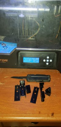
Watts-on's "SpringSlot" 18650 Battery Holder

watts-on said:
I have had this idea bouncing around my head for a while now, but since I've decided to build one ( or some :) ) of Brett's Charge/Discharge Testers, I just didn't fancyusing any ofthose single 18650 holders.
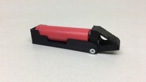
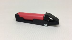
So I thought it was time to turn my idea into reality:


image_ypxxql.jpg


It has a spring loaded lever that allows you to effortlessly insert or remove a cell just by pressing it.

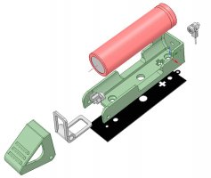
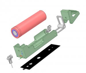
Some exploded Views:


image_qolxtw.jpg

image_vmrert.jpg


I have attached the STL files if anyone wants to 3D printtheir own.

edit:
Re-uploaded the attached zip file as a forgot to add all the files to it.

Also, I did a YouTube video too. Hope you like it. Go easy on me though, it's my first one ever :D


Wow, I so want a 3D printer. Idon'tsuppose you would sell some?

I want to redo my 20 slot TP4056 charge bay and these would be super cool. Maybe also5 slot modules would be neat.
 
chuckp said:
Wow, I so want a 3D printer. Idon'tsuppose you would sell some?

I want to redo my 20 slot TP4056 charge bay and these would be super cool. Maybe also5 slot modules would be neat.

You're not the first to ask, but to be honest, I'm not really setup for mass production. :)
I'll think about it though...
 
watts-on said:
brettwatty said:
Mate that is genius and awesome. I need some for my Charger / Discharger. Now to buy a 3D printer. Hmmm will my wife let me hmmm.........

Thanks mate. I'd send you a set, but postage from the UKis going to be eye watering.

Pete's a lot closer, and he's got a shiny new printer andneeds something topractice on... :D

Sweet look forward to it mate. Bugger now youhave forced me to build another Charger / Discharger. ;)
 
brettwatty said:
...Bugger now youhave forced me to build another Charger / Discharger. ;)

You're welcome mate, you can never have too many cell testers :D
Package is on its way..
 
CrimpDaddy said:
Very cool, i'm always impressed by these home brew DIY creations.

I could buy a 3D printer right now, what I can't buy is some 3D CAD skills...

I was worried about that too. Tinkercad (tinkercad.com) is the simplest way to get started - it's got a very simple interface and almost no learning curve.

Worked for me so far.

Cheers, Paul
 
watts-on said:
I have had this idea bouncing around my head for a while now, but since I've decided to build one ( or some :) ) of Brett's Charge/Discharge Testers, I just didn't fancyusing any ofthose single 18650 holders.
So I thought it was time to turn my idea into reality:


image_ypxxql.jpg


It has a spring loaded lever that allows you to effortlessly insert or remove a cell just by pressing it.

Some exploded Views:


image_qolxtw.jpg

image_vmrert.jpg


I have attached the STL files if anyone wants to 3D printtheir own.

edit:
Re-uploaded the attached zip file as a forgot to add all the files to it.

Also, I did a YouTube video too. Hope you like it. Go easy on me though, it's my first one ever :D


Does anyone have a list of links to the vitamins for these?
 
Found this just now.
Looks like it can carry double contacts for a 4-Wire connection as well.
(Ya know, for IR Measurement)
 
chiphead said:
Does anyone have a list of links to the vitamins for these?


Erm Not sure I understand that question. :s

Cherry67 said:
Found this just now.
Looks like it can carry double contacts for a 4-Wire connection as well.
(Ya know, for IR Measurement)

Yeah, you could use two ring tags on each of the two screws, one for current and the other for sense.


Has anyone printed any of these yet? Feel free to post pics. :)
 
sorry vitamin = non-printer parts in a printed project.

hardware. The sizes and type of nuts and bolts etc.


image_rbkyto.jpg

Printing in eSun Black PETG on my enhanced FFCP
2 down 26 to go
 
chiphead said:
sorry vitamin = non-printer parts in a printed project.

hardware. The sizes and type of nuts and bolts etc.


Ah OK, not heard that term before.
I've edited the top post to included the "vitamins". :)

chiphead said:
Printing in eSun Black PETG on my enhanced FFCP
2 down 26 to go

Cool. Thanks for posting. Looking forward to seeing the finished product. :)
 
watts-on said:
chiphead said:
sorry vitamin = non-printer parts in a printed project.

hardware. The sizes and type of nuts and bolts etc.


Ah OK, not heard that term before.
I've edited the top post to included the "vitamins". :)

chiphead said:
Printing in eSun Black PETG on my enhanced FFCP
2 down 26 to go

Cool. Thanks for posting. Looking forward to seeing the finished product. :)

thumbsup.png
TYVM exactly what I was looking for.

IIRC vitamins was used to describe the non-printed parts of the reprep. it kinda stuck for printer projects.
biggrin.png
 
watts-on said:
chiphead said:
sorry vitamin = non-printer parts in a printed project.

hardware. The sizes and type of nuts and bolts etc.


Ah OK, not heard that term before.
I've edited the top post to included the "vitamins". :)

chiphead said:
Printing in eSun Black PETG on my enhanced FFCP
2 down 26 to go

Cool. Thanks for posting. Looking forward to seeing the finished product. :)


My hardware arrived from McMaster-Carr.

As a warning to others. I ordered wooden cloths pins from amazon and the springs fit but 3m screws do not.

Ordered some 2.5mm and hope they will fit as 2m are not available long enough. Will update in a week once these arrive.

If they are still too big to fit my springs, I'll get some music wire and wind my own.
 
++ Great thread and documentation. Really nice.

Edit:
Cell holders are definitely wear items if you think about testing thousands of cells like the PowerWallers before have done.
 
chiphead said:
My hardware arrived from McMaster-Carr.

As a warning to others. I ordered wooden cloths pins from amazon and the springs fit but 3m screws do not.

Ordered some 2.5mm and hope they will fit as 2m are not available long enough. Will update in a week once these arrive.

If they are still too big to fit my springs, I'll get some music wire and wind my own.

Sorry to hear you've had trouble sourcing the springs. Have you tried unwinding one of your springs by grabbing each end in some pliers and twisting by one turn in the opposite direction to the way its wound. This should open up the bore slightly. I suspect it will distort the spring beyond use, but may be worth a try.

I didn't do any research into peg spring availability, but since I had these two types both of which are suitable I though it should be easy to find similar ones.


image_rduiqe.jpg


The green one is at least 10 years old and the blue one I bought only recently.

I trawled ebay and found a few that look remarkably similar, but obviously can't be sure they're OK.

PRO-MART-Plastic-Clothespins-24-Pack
NEW-Mainstay-52pc-Industrial-Strength-Plastic-Clothespins
96-Multi-Color-Plastic-Clothespins-2-7
HONEY-CAN-DO-Clothespins-Plastic-PK24-DRY-01390

If anyone sources suitable springs in their country, please post links here for the benefit of others. :)

Anyway hopefully your M2.5 screws will work OK <fingers crossed>


SecondHandPower said:
++ Great thread and documentation. Really nice.

Edit:
Cell holders are definitely wear items if you think about testing thousands of cells like the PowerWallers before have done.

ThanksSecondHandPower :)

Yeah, I had trouble with those standard holders with the formed contacts. When they're new I pretty much have to lever the cells out with a screwdriver, but then after a good few cells have been through them, they start to weaken and I start doubting if they are making a good connection. Then I have to tweak the contacts back to get good connections. Rinse and repeat. And thus was born the SpringSlot holder. :cool:
 
chiphead said:
watts-on said:
chiphead said:
sorry vitamin = non-printer parts in a printed project.

hardware. The sizes and type of nuts and bolts etc.


Ah OK, not heard that term before.
I've edited the top post to included the "vitamins". :)

chiphead said:
Printing in eSun Black PETG on my enhanced FFCP
2 down 26 to go

Cool. Thanks for posting. Looking forward to seeing the finished product. :)


My hardware arrived from McMaster-Carr.

As a warning to others. I ordered wooden cloths pins from amazon and the springs fit but 3m screws do not.

Ordered some 2.5mm and hope they will fit as 2m are not available long enough. Will update in a week once these arrive.

If they are still too big to fit my springs, I'll get some music wire and wind my own.

New hardware arrived and the 2.5mm work with my springs. Pics to follow.
 
OK got my hardware in and the 2.5mm screws definitely work.

Love the design, however I have a suggestion.

We are installing the spring in reverse, ie against the designed springingness. This weaken the spring action and over time I fear it will loose the strength to make a good solid connection. I already over flexed one before it was mounted to a curcuit board and the spring is dead. I'll have to tear it apart and replace the spring.

My suggesting is to modify the design to accomodate the spring in its natural state, ie the way its on the cloths pin rather in reverse. I believe this will maintain the springiness of the spring better. The holder will have to be a bit taller to accommodate the spring in that direction. The part against the base will need a deeper recess.

Do you think this is possible?

-Wayne
 
chiphead said:
We are installing the spring in reverse, ie against the designed springingness. This weaken the spring action and over time I fear it will loose the strength to make a good solid connection. I already over flexed one before it was mounted to a curcuit board and the spring is dead. I'll have to tear it apart and replace the spring.

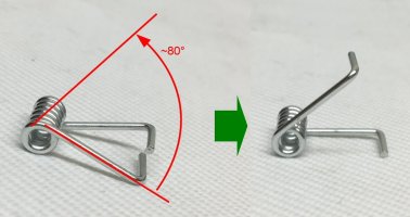
How are you reforming the springs? They should be unwound by approximately 80


image_hpnveq.jpg


I can only speak for the springs I have access to, but the spring should be just as strong after reforming as it was before and the springiness works equally well in either direction. They are pretty strong and I don't see them losing their strength any time soon. I predict they will outlast the 3D prints that I'm fitting them to.
If yours are not like that, then perhaps they are not made from suitable "springy" material. :s

chiphead said:
My suggesting is to modify the design to accomodate the spring in its natural state, ie the way its on the cloths pin rather in reverse. I believe this will maintain the springiness of the spring better. The holder will have to be a bit taller to accommodate the spring in that direction. The part against the base will need a deeper recess.

Do you think this is possible?

It's possible, but I think they would end up too large and bulky and would take more time and material to print them. I think the quickest and cheapest solution may be to have another look around and see if you can source some alternative clothes pins.
 
watts-on said:
chiphead said:
We are installing the spring in reverse, ie against the designed springingness. This weaken the spring action and over time I fear it will loose the strength to make a good solid connection. I already over flexed one before it was mounted to a curcuit board and the spring is dead. I'll have to tear it apart and replace the spring.

How are you reforming the springs? They should be unwound by approximately 80


image_hpnveq.jpg


I can only speak for the springs I have access to, but the spring should be just as strong after reforming as it was before and the springiness works equally well in either direction. They are pretty strong and I don't see them losing their strength any time soon. I predict they will outlast the 3D prints that I'm fitting them to.
If yours are not like that, then perhaps they are not made from suitable "springy" material. :s

chiphead said:
My suggesting is to modify the design to accomodate the spring in its natural state, ie the way its on the cloths pin rather in reverse. I believe this will maintain the springiness of the spring better. The holder will have to be a bit taller to accommodate the spring in that direction. The part against the base will need a deeper recess.

Do you think this is possible?

It's possible, but I think they would end up too large and bulky and would take more time and material to print them. I think the quickest and cheapest solution may be to have another look around and see if you can source some alternative clothes pins.

I understand your design and I amunwinding them as you show. That's my point unwinding instead of winding. They are stronger spring action winding instead of unwinding.
My springs are just like yours just a smaller diameter of the wound part.

My goal is not cheapest. heck a cheaper solution would bejust twowires with magnets attached but I'm not after cheap :)

I beleive using the spring in the other direction, IE winding it a bit tighter rather than undwinding the spring would.
 
hmm.. why do you believe the spring will not work in the unwinding direction? To my (possibly flawed) thinking, we are applying a ~30 twist to a 6.5 turn coil spring, so it should not care which direction the rotation is applied.

What do you have in mind for a way to use the springs unmodified?
 
watts-on said:
hmm.. why do you believe the spring will not work in the unwinding direction? To my (possibly flawed) thinking, we are applying a ~30 twist to a 6.5 turn coil spring, so it should not care which direction the rotation is applied.

What do you have in mind for a way to use the springs unmodified?


Well I don't have any scientific evidence but just my empirical observations. To test my theory, I reversed a spring in the cloths pin. I don't have a way to measure the strength but clipping an unmodified pin to my finger and then the modified one and it feels significantly weaker. after a few flexings a few dozen times its even weaker. I'm sure if I could hook up a rig to test the strength it would confirm my observations. I have already had one fail by flexing it just past vertical which I know once installed on a board won't happen but I didn't flex it farjust slightly. That's what lead me to the testing I have done.

You can try this and see if its the same for you. just reverse a spring in the cloths pin. Maybe its my springs as you suggested. I have ordered a few different types of pins to test.

I was thinking if the base was thickened the diameter of the spring and the axil moved down the same thickness to keep the top of the coil lever with the bottom, the slot for the spring in the base would accommodate the spring in its original direction. The whole thing would be just a bit taller ( the diameter of the coil spring)
 
Back
Top