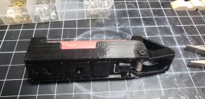
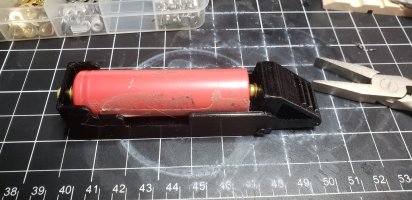
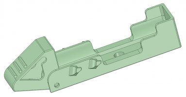
Watts-on's "SpringSlot" 18650 Battery Holder

watts-on said:
hmm.. why do you believe the spring will not work in the unwinding direction? To my (possibly flawed) thinking, we are applying a ~30 twist to a 6.5 turn coil spring, so it should not care which direction the rotation is applied.

What do you have in mind for a way to use the springs unmodified?

something like this.


image_cuplca.jpg

image_amfizc.jpg

image_vvopow.jpg
 
I'll have to check, but by moving the spring down, there may be an issue with the top spring hook clashing with where the contact screw is on the lever.

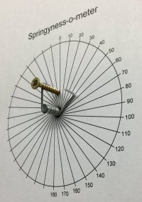
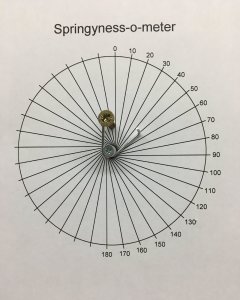
As far as the springs go, I thought I would have a go at characterizing mine, after reforming, so we have some way to compare what we have.

So I created a high tech test rig using some appropriate ballast: :D


image_iqzivi.jpg

image_shebhc.jpg


The required travel is about 30, but I'll be generous and test to around 50:


image_vamwdn.jpg

image_gaardv.jpg


So, the weight required to deflect the spring was 2 Kg.

I also cycled that 50 deflection 100 times and there was no apparent deformation compared to when I started.
 
OK, let me try this way.

As the spring is installed in the clothespin, the clamping force is applied by the spring wanting to get back to an uncoiled state. That provides the force. When you open the cloths pin, your winding more force into the spring.

Reversing this, your helping the spring to naturally uncoil. The force is for it to coil itself which is against its natural tendency to uncoil.

While you test certainly shows the spring returning to its starting position, there is no resistance to keep it from doing that. I believe if you had a load-cell measuring the clamping force, you would see diminishing force after flexing the spring in the uncoil.
 
image_aytwee.jpg


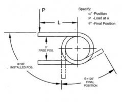
Looking up design standards for torsion springs

As load is applied to a torsion spring, the springs diameter will decrease, reducing the outside and inside diameters. The spring will also grow in length. In most cases is it wise to design for a torsion spring to wind in the direction of the coil winding. Should design require that the torsion spring wind in the unwinding direction, maximum load should be and degrees of wind should be lowered.

Good design dictates that torsion springs should be used in the direction that winds the coil.
 
Well, of all the directions this thread could go in, I would never have guessed spring physics would be one of them. :D

Fascinating stuff. You're forcing me to think hard about something I hadn't previously given too much thought to.

My Materials Technology classes were nearly 40 years ago, so I don't remember much, but one thing I do recall is that all materials have a yield point. If you stress a material below that point it will always return to its original shape when released and should be repeatable indefinitely.
The only exception being if there are flaws or inclusions in the material that concentrate the stress and lead to fatigue and eventual failure. But even that is still obeying the yield point limits since in reality the material around the localised stress point is being subjected to stresses that take the material beyond its yield point.

I totally get that a torsion spring would perform better when wound tighter compared to being unwound. The circumference of the outside is greater than the inside, so there is more material in tension and therefore more force and travel before the yield point is reached. So you can achieve your required spring force using less material using that configuration. (more spring for your buck).

chiphead said:
While you test certainly shows the spring returning to its starting position, there is no resistance to keep it from doing that. I believe if you had a load-cell measuring the clamping force, you would see diminishing force after flexing the spring in the uncoil.

I'm not sure I agree with that assessment. If the spring returns to its original position as in my test, then it has not experienced any deformation. For it to suffer gradual loss of tension, it would need to have deformed (exceeded its yield point) which would be evidenced by it failing to return to its starting point.

Chablis_m said:
Should design require that the torsion spring wind in the unwinding direction, maximum load should be and degrees of wind should be lowered.

I believe my springs are operating in this region. E.g. not ideal, but ok since I'm operating them with low deflection and accepting reduced force.

I pondered how best to use the springs before creating the design. I figured if I used them as is, they would need to be sprung quite a bit tighter to reach the 80 to 110 ish operating angle. I felt that the tension was way higher than required to achieve a decent contact pressure on the cell and would potentially lead to unnecessary stresses on the plastic parts. I concluded I would need to reform the spring even tighter to remove some of that tension. So, if I had to reform the springs anyway, I figured unwinding it and using it in the opposite direction gave several advantages:

  • The tension was reduced to a more acceptable level.
  • The design was simplified since only a small clearance was required under the main body to accommodate the lower hook.
  • The core of the spring opened up just enough to accommodate a M3 thread, giving a larger bearing surface for the pivot, since a screw thread is far from an ideal bearing surface anyway, especially in plastic.

As I stated before though, I can only go by the springs I have, which clearly have very different characteristics to yours. I don't know it I was lucky and got the only ones in the world that are suitable, or you were unlucky and got the only ones that aren't. Unfortunately, even though 78 people (at time of writing) have downloaded the .STL files, no one else has come forward to report their experiences, good or bad, with their springs.

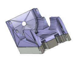
I've attached a new version for you to try, that should accept your springs unmodified. I managed to only increase the height by 4mm and the length by 1mm. And there doesn't seem to be a problem with clearance of the top hook like I thought there might be.

I printed one out just to check everything worked, and tested it with a fresh, unmodified spring. I then did a tension test so we have something to compare. With the unit screwed to a vertical surface and a chord pulling the lever at the location of the terminal screw required a weight of 3KG :exclamation: to pull the lever until it was 90 to the base.


image_gwjidd.jpg

image_oorphw.jpg
 

Attachments

  • SpringSlot_Alternate_Ver1.zip
    78.8 KB · Views: 290
watts-on said:
I've attached a new version for you to try, that should accept your springs unmodified. I managed to only increase the height by 4mm and the length by 1mm. And there doesn't seem to be a problem with clearance of the top hook like I thought there might be.

I printed one out just to check everything worked, and tested it with a fresh, unmodified spring. I then did a tension test so we have something to compare. With the unit screwed to a vertical surface and a chord pulling the lever at the location of the terminal screw required a weight of 3KG :exclamation: to pull the lever until it was 90 to the base.
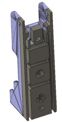
Thank you!Exactly what I wanted! Works perfectly. Nice tight snappy action. Very strong grip on the battery. And 2.5mm screws fit my stock springs as well. I incert the screw before flexing the spring for insertion. Works fantastically. Now to print 27 more and toss the 28 I previously printed.

Thank you again!


image_wasrys.jpg

image_wdhcgc.jpg

image_ovcnum.jpg

image_aeoauc.jpg
 
chiphead said:
I have ordered a few different types of pins to test.

Did your alternative pins arrive? where they any different? Maybe there his hope to save your existing prints?
 
watts-on said:
.................
As I stated before though, I can only go by the springs I have, which clearly have very different characteristics to yours. I don't know it I was lucky and got the only ones in the world that are suitable, or you were unlucky and got the only ones that aren't. Unfortunately, even though 78 people (at time of writing) have downloaded the .STL files, no one else has come forward to report their experiences, good or bad, with their springs.
..................

Printed in the UK with the springs attached as suggested by watts-on and they function well. Assuming chiphead is from over the pond by his referring to the 'clothes pins' perhaps there is a material diffeence between a 'clothes pin' and a 'clothes peg'.

My only issue is with 'protected cells' the lever opens beyond horizontal but this may be due to the head size of the bolts I am using, will try some other bolts some time.
 
trikidiki said:
Printed in the UK with the springs attached as suggested by watts-on and they function well. Assuming chiphead is from over the pond by his referring to the 'clothes pins' perhaps there is a material diffeence between a 'clothes pin' and a 'clothes peg'.

My only issue is with 'protected cells' the lever opens beyond horizontal but this may be due to the head size of the bolts I am using, will try some other bolts some time.

Thanks for the info trikidiki.
I too wonder if there is some difference in materials between pegs/pins.

I designed in a bit of wiggle room to account for cell length, by using a washer under the head of each screw that I would then have the option to remove (or even add more) if necessary. Alternatively, maybe filing the heads down a bit might be the way to go, depending on how many you are making.
 
100kwh-hunter said:
My wife won't be pleased, when she finds out who has the peg's.

My wife was more positive. She handed me the few pegs she had and said here you go..... now I can go buy myself some new ones.
Oh Boy should have seen that one coming.
In the end the springs were a different size so she might slowly loose the new ones too.
 
watts-on said:
trikidiki said:
Printed in the UK with the springs attached as suggested by watts-on and they function well. Assuming chiphead is from over the pond by his referring to the 'clothes pins' perhaps there is a material diffeence between a 'clothes pin' and a 'clothes peg'.

My only issue is with 'protected cells' the lever opens beyond horizontal but this may be due to the head size of the bolts I am using, will try some other bolts some time.

Thanks for the info trikidiki.
I too wonder if there is some difference in materials between pegs/pins.

I designed in a bit of wiggle room to account for cell length, by using a washer under the head of each screw that I would then have the option to remove (or even add more) if necessary. Alternatively, maybe filing the heads down a bit might be the way to go, depending on how many you are making.

The bolts I had of the right length are hex-head and the heads are quite large. Filing was my first thought as it may also give me a larger contact area too. Failing that I'll try some round head bolts or even countersunk ones. If all else fails I'll remix your STL file and increase the length very slightly.

Will be trying a four cell version with the PCB slots at the weekend.
 
I also found that the lever is tilted back using normal sized PC case bolts. These are shallow and rounded. But this is ok
 
trikidiki said:
The bolts I had of the right length are hex-head and the heads are quite large. Filing was my first thought as it may also give me a larger contact area too. Failing that I'll try some round head bolts or even countersunk ones. If all else fails I'll remix your STL file and increase the length very slightly.

Will be trying a four cell version with the PCB slots at the weekend.

I think the screws I use are called cheese head.

trikidiki said:
Do you have a link for the four cell with charge board version?

It's included in the zip file with the others. Named "4_Gang_SpringSlot_Ver1.stl".
 
watts-on said:
trikidiki said:
The bolts I had of the right length are hex-head and the heads are quite large. Filing was my first thought as it may also give me a larger contact area too. Failing that I'll try some round head bolts or even countersunk ones. If all else fails I'll remix your STL file and increase the length very slightly.

Will be trying a four cell version with the PCB slots at the weekend.

I think the screws I use are called cheese head.

trikidiki said:
Do you have a link for the four cell with charge board version?

It's included in the zip file with the others. Named "4_Gang_SpringSlot_Ver1.stl".

Cheers, I looked at it in Cura and didn't see the board slots on the back, so assumed there was another file with the board slots. Now I've altered the view I can see they are there.

Cheers
 
Hey Watts-on, Would it be possible to o put nubs on the side to allow an elastic as an alternative to the Springs for those who are having issues sourcing the right springs?

Also, if the lever extended to under the 18650, pushing the lever could help pop the cell up making it easier to grasp.
It may also hold the lever in the open position waiting for the next cell to be inserted. And with one hand operation vs. 2 hand operation required when using a spring.

Thanks.
 
100kwh-hunter said:
wish you also made a 10 or 12 slot.

best

You mean instead of the 4-slot version?

What if I separate out the sections, and then you can arrange as many as you like in your slicer to create one of any size?


Bubba said:
Hey Watts-on, Would it be possible to o put nubs on the side to allow an elastic as an alternative to the Springs for those who are having issues sourcing the right springs?

Something like this: ?


image_asigmv.jpg


The nubs might look a bit strange, but I did them like that so they will print without any supports.
I haven't tried printing it, but have attached the .stl files if you want to give it a try.

Bubba said:
Also, if the lever extended to under the 18650, pushing the lever could help pop the cell up making it easier to grasp.
It may also hold the lever in the open position waiting for the next cell to be inserted. And with one hand operation vs. 2 hand operation required when using a spring.

Thanks.

Hmm, that sounds harder, but a neat idea. I will see if I can come up with something.

Darn, I'll have to rename it now to "ElasticSlot"! It just doesn't have the same ring to it. :D
 

Attachments

  • ElaticSlot_Test1.zip
    111.7 KB · Views: 229
Back
Top