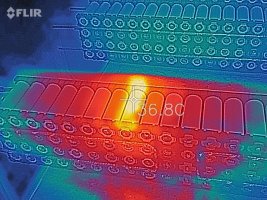
The one thing I have often wondered about is the whole issue of soldering to the -ve side of the cell with a large soldering iron creating a lot of heat into the cell. The cells all (appart from the odd one or two) seem to have good flux flow indicating good heat, but given Li cells don't like hot conditions and degrade very (relatively) quickly, prolonged soldering iron contact to me is an interesting situation. The +ve side of the cells tends to be spaced off away from the internal chemicals so less of an issue.
Spot welding creates high very localised temperatures with a low depth of heat dissipation, very unlike a large soldering iron held on the cell for a few seconds to get the flux to flow at upwards of 180C/360F (enough to boil electrolyte).
Maybe a complete non issue due to the lack of similar issues from DIY builds, just a thought and question that I have often wondered about.
Li cells almost seem to be like nuclear reactors in terms of thermal runaway.....
The safest and best environmental (temperature) location to me is to dig a hole a couple fo meters deep and put the cells in... temperature is stable yearr round and nothing to burn.


")