Various Flashlights And Things Get 18650ed, Part 2

Joined
May 25, 2017
Messages
554
I guess we can't post to old threads anymore. :(
So here's a continuation of:https://secondlifestorage.com/showthread.php?tid=2012&pid=11351#pid11351

Helmet audio project:

When I ride my motorcycle long distances, and have to get to a specific location, I like to use my cell phone's Google Maps app. But I can't hear a thing because of the wind and engine noise.

I also can't afford all that fancy blu-tooth stuff they make for bikers. So I'll make due with various bits of junk and cheep things I've got laying around.


First I got some speakers for the helmet. I don't have pictures of that yet, so I'll skip to the part where I discovered I'd need an amplifier...

Found this tiny amplifier super cheap from China. Some assembly required, but that's part of the fun, yes?
image_cdircg.jpg
The directions were surprisingly easy to read.
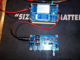
image_cnkqrc.jpg
Now, I don't know much about amplifiers. But here I'm trying to see how much current it needs. At 12V, it's drawing less than I can measure. Maybe it uses more when there is actual sound going through it? In any case, a 3s1p 18650 battery should be plenty to power it. I tested the device on the full range of such a battery, and it works fine.

I thought about just plugging it into the motorcycle's electrical, but then I'd have yet another cable attaching me to the bike.
image_pfknle.jpg
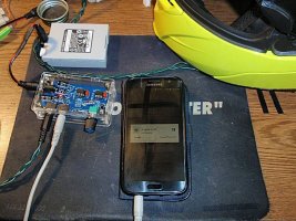
Here it is with the acrylic case that came with it, and some cables I used to try it out. Works great, with very clear sound, and it definitely makes audio signals louder. If the input is too strong, the sound will start to break up at full volume, but it seems to work well with my phone.

See, I have this issue where the phone will default to about 80% volume without my asking, when I need 100%. It's an annoying safety feature. But it works out well, because the volume it keeps defaulting to is about as loud as the amp can handle. So I can have the amp at max volume without the sound breaking up.

I gotta take more pictures, but later I'll post about the helmet and the DIY 18650 battery I made for it.
 
Got some pics of the helmet speakers.

image_dxvxbk.jpg

These came from a couple broken GPS units that I bought to repair the one I have that had a cracked screen. The cells and speakers were good in both, so I salvaged them too. Since they're identical, they work well in stereo. I'm no audio expert, but I know that different speakers have different impedance, and if they are mismatched, they won't sound right.

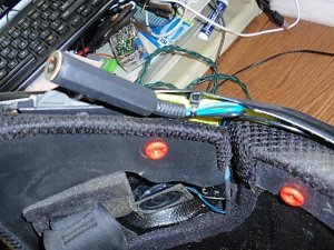
Anyway, the wires all tucked nicely into the back of the helmet, and there was even a little hole that was preformed in the plastic that was perfect for a strain relief zip tie.

image_vosgpg.jpg

Early on, I had problems with the 1/8" jack coming loose from the helmet. I've replaced it with a 1/4" jack, hoping it will be more solid. Everything is nicely hidden beneath all the removable padding, and just the jack shows.

Also made my own audio cable. One reason is that I had the parts. Another is that I was able to use some old Christmas light wire which is much more robust that your typical audio cable. A third reason is that the connectors are easily repairable if that should be necessary.

image_prkyim.jpg

I braided it my self. Looks cool, and also keeps the wires from flopping around.
 
So, finally, the battery.

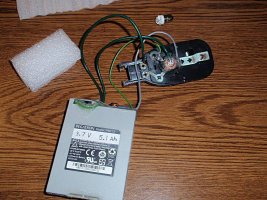
I have a whole box full of these empty Pegatron battery shells which came apart intact enough to reuse.

image_lyevwn.jpg

I tested several of the original circuit boards, and they were all bad. With a little modification, a generic 3s BMS board will fit in the same space.

image_ibzipc.jpg


image_zhuxja.jpg

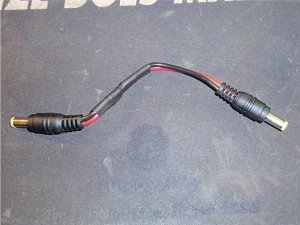
I made sure the amplifier and the battery had the same connector sizes, so all I had to do was build a short patch cable to connect them.

image_gqinsp.jpg


image_wfqukz.jpg

I haven't had it on the road yet, but it's all working so far. I'll have to get some Google map directions going at some point, since being able to hear that is the whole point of the project.

image_hvxmqt.jpg

For now, I can hear that having the phone on it's default volume, and the amplifier on full, gives nice sound and is significantly louder than if the phone were hooked up directly at full volume.

Looking forward to a real world test. :)
 
This one won't count towards being second life cells, since they're new. But I thought I'd share anyway.

I bought six 20A cells. Five to rebuild a battery for a drill I picked up at a thrift store, and one to replace the NiCd cells in my electric screwdriver. I posted about that one a while back, replacing old NiCds with new NiCds, but I was still not happy with the way they would self discharge in between uses.

Anyway, I don't know if this will be interesting or not, but here it is.
 
Vintage multifunction light gets LEDed and 18650ed.

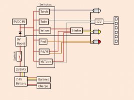
You know I love making diagrams, so here is the one for this project:

image_peocng.jpg


This was a little more involved than a normal flashlight, but was still fun to do. I tried some different cinematography, and I think it's kind of ok. I like the perspective from the camera on my shoulder, but with the time compression, all the movements are exaggerated. I'll keep that in mind for future projects. Never could figure out YouTube's public domain music feature, so I found my own, and added it in through my video editor.


I'm pretty happy with the way this turned out. This one came from a thrift store, but my grandpa has a light just like it, so I'm looking forward to showing this to him. It all runs off voltage boosters and Li-ion instead of bulky D cells now. And it's all LED, so it should last something like 15 hours per charge.
 
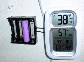
In the older thread, I 18650ed my little digital weather station.
PA290009.JPG

That was in October 2019. I've been meaning to test the Voltage of the single cell that has been powering it, and realized it's been over a year. Turns out the cell is still at 3.84V. About the same as it was when I installed it. The weather station seems to take almost no current. I guess I'll leave it until next October and measure again, LOL.
 
Last edited:
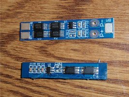
Update on the utility light. The BMS I installed shut off and wouldn't start up again. I bought some new 2s BMSs for other projects, so I was able to replace it quickly. Interesting though, the new BMSs are larger with two extra ICs on them than the old one.
P2060004.JPG

I should probably learn more about what the different parts of BMSs do. It would probably help me buy better ones in the future. I think the old one had voltage and current protection only. The new one may also have balancing?

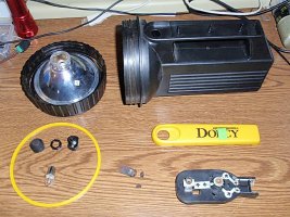
Anyway, I found another utility light at a thrift store, and decided that it needed me. I've got it all disassembled for cleaning, and the obsolete parts have been removed.
P2060001.JPG

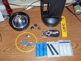
I've got some LED bulbs to replace the old incandescent ones. This time though, I'm making the whole thing 12V so I only need one regulator. And I found a silent LED blinker relay that works better than the mechanical one I bought for the first light.
 
I have a lot of flashlights around the house in case of power outages. We usually have at least one per year in the winter because of wind storms. Problem is, they're all incandescent and use D cells. And they're always super dim by the time we need them. So I'm looking to convert some to LED and Li-Ion. Here's one that had water inside at some point. Got it all apart and started cleaning it up.

P2050001.JPG

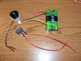
I used a 1s BMS, Volt booster board, and a TP4056 board.

P2050002.JPG

I decided to go with a 4.5V LED, and a 1s3p battery. Since the flashlight has plenty of room inside, I put the cells in a case. I have 30 of these little cases from some cells I harvested a while back.

P2050003.JPG

The way I wanted to wire it up, was so the booster board would be shut off by the switch. They draw phantom power, and can drain the battery over time. With the booster board disconnected, the cells should stay charged indefinitely.

P2050004.JPG

I used a bunch of hot glue to insulate the connections and keep everything in place. I put a couple pieces of foam inside the housing to keep the battery from moving around, and even wrapped the battery in foam for a little extra protection. The battery still pops out though for charging. I decided to leave it this way because the casing is water resistant, and I wanted to keep all the electrical connections inside.

P2050005.JPG

The BMS fit inside the box no problem. The charger and booster though, will have to live outside.

P2050006.JPG

After some math, it looks like a fully charged battery could run for over 80 hours. And it's plenty bright. :)
 
Always thought to convert one of these big flashlights to something with LED and 18650s.
 
I did the same for the IR-sensored 10x led night lamp in the loft. I removed those skinny 4x AAA 1.5V batteries and put a nice 1s2p 2200mAh 18650 batteries in an external box. It runs perfectly with 4V and lasts a lot longer(y)
 
Cool. I really like these small projects. Especially when you end up with something useful. :)

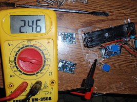
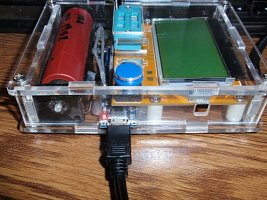
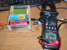
I went to use my parts identifier/checker thing the other day. The one I modified a while back to use an 18650 instead of a 9V battery. Wasn't working right and wouldn't charge, so I started poking around. Unfortunately, I broke the TP4056 board while I was testing it, so I ended up replacing it.
P2070001.JPG

For single cells, I like to charge them at 500 mA maximum, so the control resistor gets replaced with a variable resistor set to about 2,500 Ohms. Easier on the cell, and less heat from the TP4056 chip.

P2070002.JPG

I also wanted to add a switch between the TP4056 positive out and the booster board's positive in. That way, I can turn it off and it won't draw phantom power while I'm not using it.

P2070003.JPG

After a lot more poking around, I found the issue I was having was a bad connection on the negative side of the battery holder. That was easy enough to solder up. Now I've got a good connection to both the charger and the booster board.

P2070004.JPG

One more thing I did while I had it apart was to add a couple holes in the sides that multi-meter probes can fit through. This way I can test the voltage of the cell for troubleshooting purposes.

P2070007.JPG

I think I tinker with this gadget more than I actually use it, LOL. But I do find it very handy. I have boxes full of vintage electronics bits that a friend gave me, and it's nice to double check that they still work before using them.
 
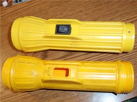
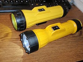
I got more flashlights at the local Habitat store. The two I worked on this time cleaned up really nice in the dishwasher.
P2270003.JPG

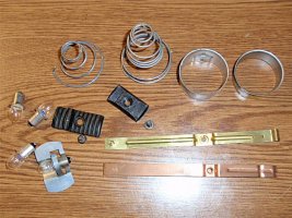
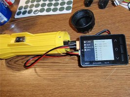
I had to widen the switch hole just a bit to accommodate the new switches. I also pulled out all the unnecessary hardware. I might be able to use the springs and the brass and copper strips for future projects.
P2270004.JPG

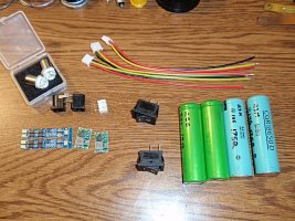
New hardware. BMSs, buck regulators, cells, switches, LED bulbs, barrel connectors, and balance cables.
P2270002.JPG

I decided to go with 2s batteries because they just barely fit, and the buck regulators will always have a higher voltage to buck even if the cells are depleted. Of course, if they get that far, the BMSs will shut them off. The extra balance cable is for an extension to make reaching chargers easier.
P3040006.JPG

I've also just started putting extra insulators on the positive end of my cells. An easy and cheap safety feature that I should have adopted years ago. The LED bulb is 4.5V, and 0.05A, so the buck board can handle that easy.
P3040012.JPG

Made sure the barrel connector and balance cable did their jobs.
P3040009.JPG

Did almost the exact thing for both flashlights. One has a yellow lens, and the other is colorless. Both are plenty bright for our needs.
P3040014.JPG

The one with the magnet will now live on our refrigerator. The other has a ring on the end and will hang from the hat/key rack in the hallway.
P3040010.JPG

These two flashlights will last 50 hours between charges, and being Li-Ion, will have pretty much no self-discharge between uses.
 
LOL I love all this stuff you make:)

Here, I'll share with you my 2s1p powerbank for Arduino boards. It has two outputs (Arduino is happy with voltages between 7 and 12V DC) and an input connector to recharge batteries. And a push button and a display to check battery voltage. Box is a 0.80$ 70x40x35mm from AliExpress. But don't ask... I can't give you my secret schematics LOL!

battery-pack-1.jpgbattery-pack-2.jpg

To get the maximum out it I started using low power/sleep mode in Arduino code. Yes, it could easily become a powerbank to charge cell phone, I love it!

Night after I made another tiny board for backup power when electricity goes... This was just a PoC, I want to make something a bit more complex here because I have a load of devices running on 12V (cams, routers, etc) and I want them to stay on when electricity goes.

Backup-DC-Power-1.jpgBackup-DC-Power-2.jpg
The load (2x 20mA displays) work with DC power supply, and if that goes off will continue working from 3s1p battery pack, no switches, no relays. Being just a test I obviously want to make it safer and solid by adding a proper charger and voltage protection, and a better protection between the two "power rails". If the diode blows it would be a mess:D

jes
 
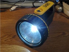
Here's one I've been thinking about doing for a long time, and finally got started: a Cyclops flashlight that I inherited from my grandfather.

P7210001.JPG

It's basically a portable headlight. It even has high and low beam settings. I've already switched out the 9003 headlight bulb with an LED equivalent. Actually works pretty good. I used it many years ago, strapped to my sidecar during a nighttime off-road excursion. Also lit up the inside of a moving truck really good when I was helping my neighbors pack. And no extension cord needed. :)
P7210002.JPG

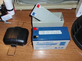
Runs on a regular SLA battery, and can also be plugged into a vehicle's 12V system directly. Came with a charger too, but I'm not sure where that is. I found this SLA shaped box designed to hold 21 18650 cells, so I plan to replace the lead battery with that. The LED light uses 2.25A high, and 1.5A low. So a 3s7p battery could potentially run for 6 hours between charges on high. Or 9 hours on low. Depending on the cell capacities. I wonder if I should put it on a booster to make sure it gets a constant Voltage. My understanding is that LED headlights are supposed to have "drivers" between them and the car's power to make sure they don't burn out prematurely.

Anyway, I opened it up to have a look at the circuitry inside. Looks like I pulled a wire loose from one of the switches though. Looks like power goes to both switches, one for high, and one for low. Turning them both on at the same time just does high.
P7210003.JPG

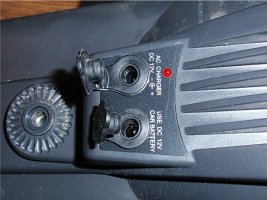
There are two connectors for power input. Ones is for a car's power, and the other is for an AC charger.
P7210004.JPG

Turns out they share a circuit board, but seem to have different functions. I'm not super fluent in electronics, but I can guess a little how it works.
P7210007.JPG
P7210008.JPG

The negatives are all connected directly together. The positives from the battery and the car input and power out to the LED are also all directly connected. The AC charger input is much more complicated. There is a big diode and two small ones, several resistors, and 3 ICs with 3 pins each. And also an LED indicator.

I wonder if the big LED prevents the Light from running off the AC charger. I'm guessing all that other stuff is there to cut off the charging of the battery once it reaches a certain Voltage. Whereas it wouldn't hurt the car any to charge the battery and run the light at the same time. Wouldn't need a cutoff for the light's battery any more than the car's battery would. I'm sure one of those resistors keeps the indicator LED from burning out from the 12V.

P7210006.JPG

My best guesses anyway. I checked the Voltage after the car input and the charger input to the battery. No Voltage loss from the car input. The charger input lost 0.2V, probably because of all the extra circuitry. I didn't think to check the effect on the output to the light. I bet the charger input never reaches it.

Now that I have a better idea on how it all works, I think I will put a diode between the car input and the battery. And probably fill the AC charger input in with hot glue. I don't want this kind of unregulated power going into a Li-Ion battery. I'll add charging and balancing ports directly on the new battery. And the light can still be run directly from a car or other 12VDC source.
 
In the older thread, I 18650ed my little digital weather station.
View attachment 22849

That was in October 2019. I've been meaning to test the Voltage of the single cell that has been powering it, and realized it's been over a year. Turns out the cell is still at 3.84V. About the same as it was when I installed it. The weather station seems to take almost no current. I guess I'll leave it until next October and measure again, LOL.
It's been another year, and the weather station is still running on the same cell. It's down to 3.75V now. At this point, I'm really curious how long it will last. And what the current is on the weather station. So far, the math says it's using 0.0001A or less. So 0.1mA. I don't know, maybe this is dumb, but I get a kick out of it. :)
 
Some of my latest:

3x18650 for string LED emergency lights. Sting on the upper side of the door of each room. In case of power outage. the 12V LED string can be turned on independently of anything.

3x18650 for old army 12V walkie-talkies. These are really good, was worth to convert them.

8x26700 LiFePo4s as replacement for the 12V lead UPS battery.
 
Finished up the Cyclops. I put a diode in so the Li-Ion battery can't be getting "charged" from an external charger or from the 12V car power jack. The charger jack is now unused, and the car jack only powers the light bulb. The new battery is set up to charge from the back without having to be removed.
PB210005.JPG
PB210006.JPG
PB210007.JPG
PB210008.JPG

I still need to put a label on the back of the battery so I know what charger settings to use.
 
I found an old pair of walki-talkies among my grandfather's things. They run on AAA batteries, which in my experience are terrible. I think these are going to get 18650ed soon. :)
 
Well, I collected a few bits, and got those walki-talkies 18650ed.
P5070030.JPG


I maybe could of used a smaller prismatic cell that would have fit in the battery chamber, but I have hundreds of old 18650s lying around, so I want to use them. These use 4 AAA cells in series, so the voltage range is about 4-6V. I installed a voltage regulator set to 5.5V, and attached it to the wires feeding the circuit board.
P5270032.JPG

P5270034.JPG

I drilled two screw holes for the battery holder, and two more for the new wires.
P5270033.JPG

Voltage regulators use a tiny bit of power even when not in use, so I added a switch between the battery and the regulator so it doesn't get drained between uses. I wouldn't think the regulator could drain an 18650 very fast, but I've had just that issue with projects in the past.
P5270035.JPG

The battery holder almost snaps right into the bit where the belt clip would attach, so between that and the screws, it's pretty secure. I made sure the screws were short and didn't go anywhere near circuitry. Normally I'd add a basic BMS to protect against under voltage, but I decided to also add on of those TP4056 charging boards with battery protection built in.
P5070031.JPG

I added hot glue or electrical tape to various areas to prevent accidental contacts and hold stuff in place. Now the battery can be charged via a cable, or just replaced with a fresh charged one if time is an issue.
P5270037.JPG

P5270036.JPG

The flash washed out the display, but they work. These will come in handy this summer when by boy and I are renovating the attic.
 
Now to 3D print a new back for them so they look like a complete unit :p

Job well done (y)
 
Back
Top