watts-on
Member
- Joined
- May 27, 2017
- Messages
- 198
With most Grid-Tie inverters, there is no way to regulate the amount of power they generate. They are designed to convert the maximum amount of power they receive at their input, into output power.
The Grid-Tie Inverter with Limiter (GTIL) units however, have the ability for the output power to be regulated.

This is achieved via one of two methods. The analogue input using a current transformer (called internal), or the digital input, intended to be used by a separately available external control box (External Limiter)


Unfortunately, what it doesnt have, is the ability to regulate the output under software control in real time. It does have a communication port, but as far as I can tell, there is only basic settings and statistical information available. No real-time control seems possible.
I wanted the ability to control the output myself under software control, so I set about designing my own DIY control unit.
After investigating how the digital control input works, (which I wrote about here) I created my design:
The principle is that I measure the mains voltage and current flowing through my board, and then control the digital input to the GTIL to either increase or decrease the power to reach that requested by the user.
I thought that generating the digital signal, which appeared to be some kind of weird PWM, was going to be hard. But it turns out it is way easier than I was expecting. It is nothing so grand as PWM, but simply a balance between what you want and what you are getting. To sum it up:
1. Approximately every few hundred milliseconds compare the measured power with the requested power.
2. If measure is too high, set signal high
3. Else set signal low.
So as the power hovers around the requested set point, that changing (PWM like) high/low signal is produced.
My test rig:

The following two scope traces show the control signal changing, as I request power from 100w to 200w, and vice versa. For example, on the left image at the point where I request the increase to 200w, the signal goes low and stays low, while the inverter slowly ramps up the power over several seconds. Once it reaches 200w it goes back to balancing it around that point.

So although Im calling this real-time control, it is limited by the rate of change that the inverter itself achieves, plus the time for my whole house monitoring system to notice a change and update the requested power.
Also, I noticed that it isn't stable when outputting 40w or less. I also checked that with the commercial external limiter unit and it is the same, so that is a limitation of the inverter itself and not the control method.
I can't go much above 200w right now due to the limited wire gauge I used on my test battery bank, so will need to get my proper diy power wall up and running before I can test it at the full 2000W.
The image below shows the board running:

The left column shows the measured data: Voltage, Current, Real Power, Apparent Power.
The right column shows the control registers I use, which I send to it over RS485 ModBus: The first 3 are calibration values required for accurate measurements (voltage, current and phase angle), and the final value is the user requested output power in watts.
Real Power shows as negative when power is flowing from the inverter to the grid.
To measure mains voltage, I am using a ZMPT101B module:

eBay Examples
Initially I was just using the transformer, but in trying to get that part of the circuitry working, I realised I was just reinventing the wheel, so now I am using the complete module.
The current is measured be feeding the live wire through a 10A current transformer. 93 Ohms and a 1000:1 turns ratio:

From RS Components
The code is Arduino based, and Im utilising the EMonLibCM library to pull the readings from those components and give some numbers I can work with.
EmonLibCM
Ive also added an on-board relay in-line with the mains which will allow me to disconnect the mains supply when not in use to save power. I havent check yet, but I suspect it will still draw a small current from the battery in this state though.
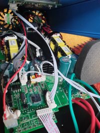
A couple more pics:


The Grid-Tie Inverter with Limiter (GTIL) units however, have the ability for the output power to be regulated.
This is achieved via one of two methods. The analogue input using a current transformer (called internal), or the digital input, intended to be used by a separately available external control box (External Limiter)
Unfortunately, what it doesnt have, is the ability to regulate the output under software control in real time. It does have a communication port, but as far as I can tell, there is only basic settings and statistical information available. No real-time control seems possible.
I wanted the ability to control the output myself under software control, so I set about designing my own DIY control unit.
After investigating how the digital control input works, (which I wrote about here) I created my design:
The principle is that I measure the mains voltage and current flowing through my board, and then control the digital input to the GTIL to either increase or decrease the power to reach that requested by the user.
I thought that generating the digital signal, which appeared to be some kind of weird PWM, was going to be hard. But it turns out it is way easier than I was expecting. It is nothing so grand as PWM, but simply a balance between what you want and what you are getting. To sum it up:
1. Approximately every few hundred milliseconds compare the measured power with the requested power.
2. If measure is too high, set signal high
3. Else set signal low.
So as the power hovers around the requested set point, that changing (PWM like) high/low signal is produced.
My test rig:
The following two scope traces show the control signal changing, as I request power from 100w to 200w, and vice versa. For example, on the left image at the point where I request the increase to 200w, the signal goes low and stays low, while the inverter slowly ramps up the power over several seconds. Once it reaches 200w it goes back to balancing it around that point.
So although Im calling this real-time control, it is limited by the rate of change that the inverter itself achieves, plus the time for my whole house monitoring system to notice a change and update the requested power.
Also, I noticed that it isn't stable when outputting 40w or less. I also checked that with the commercial external limiter unit and it is the same, so that is a limitation of the inverter itself and not the control method.
I can't go much above 200w right now due to the limited wire gauge I used on my test battery bank, so will need to get my proper diy power wall up and running before I can test it at the full 2000W.
The image below shows the board running:
The left column shows the measured data: Voltage, Current, Real Power, Apparent Power.
The right column shows the control registers I use, which I send to it over RS485 ModBus: The first 3 are calibration values required for accurate measurements (voltage, current and phase angle), and the final value is the user requested output power in watts.
Real Power shows as negative when power is flowing from the inverter to the grid.
To measure mains voltage, I am using a ZMPT101B module:
eBay Examples
Initially I was just using the transformer, but in trying to get that part of the circuitry working, I realised I was just reinventing the wheel, so now I am using the complete module.
The current is measured be feeding the live wire through a 10A current transformer. 93 Ohms and a 1000:1 turns ratio:
From RS Components
The code is Arduino based, and Im utilising the EMonLibCM library to pull the readings from those components and give some numbers I can work with.
EmonLibCM
Ive also added an on-board relay in-line with the mains which will allow me to disconnect the mains supply when not in use to save power. I havent check yet, but I suspect it will still draw a small current from the battery in this state though.
A couple more pics:
")