Wiring for 72v battery terminals - how to connect?

garolittle

Member
Joined
Oct 27, 2017
Messages
100
I recently finished a project duringwhich I upgraded the motor and charge controller on a Razor Ground Force Drifter. Specifically, I added a 48v 1,000W motor and charge controller to the go kart and powered it with a 14S9P 18650 battery pack.
As you can see from the picture below,I soldered 12 AWG to the positive and negative terminals which led to the charge controller. My next project will involve a larger go kart using a 72V motor/charge controller and a 72V 18650 battery pack. I would like to use larger wires (8 AWG or 6 AWG) but I believe the wires willbe too large to connect toterminals using solder. Does anyone have an idea of how to safely attach the larger gauge wire to the battery terminals? Thanks for any advice you can offer.
image_tdclld.jpg
 
how many amp is the 72 v motor? or the watts if you know
later floyd
 
garolittle said:
I would like to use larger wires (8 AWG or 6 AWG) but I believe the wires willbe too large to connect toterminals using solder. Does anyone have an idea of how to safely attach the larger gauge wire to the battery terminals? Thanks for any advice you can offer.

You pretty much attached the way I was thinking of. The downside is that the solder joints aren't as good as they should/could be. A few of your joints are a little cold. You could try using a piece of nickel strip and solder the wire to it first, the more solder along the wire, the better. Then spot weld that strip to the other strip. Doing it that way you'd be able to apply plenty of solder without heating up the cells.
But, the downside is, 1) you need to make sure the nickel is straight when you solder 2) it's gonna use a lot of solder.
 
I saw this a while ago but never thought it cold be used on the batteries.I think if one were to use sheet copper and a nickel strip this method of soldering might work with a spot welder.
Cold joints might even be eliminated with this method.

later floyd


maybe not for every situation but where you have a nickel strip connecting several cells in parallel you could use a piece of ribbon solder, copper strip the same size of the nickel strips then another nickel strip on top of the copper and use the spot welder to melt the solder.
Later floyd
 
WOW - I like the spot welder in the vid !

If you have nickel strips (and a spot welder) then just extend the strips away from the cells so that you can solder without heat transfer to the cells.

In your image I would have put 2 strips across the top and then 3 or 4 strips off to the side (up in the image) to solder to rather than solder directly onto the top of the cells..

The base/top of the pack is then completely flat and the connections are on the sides, this may be easer to box/fit.

If you have a large current then double/tripple the strip to the wiring or take off at each end.

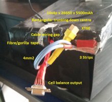
In my 10s4p I ended up spot welding 2 layers of strip between cells and 3 layers for the end connections at just one end of the pack.
 
floydR said:
how many amp is the 72 v motor? or the watts if you know
later floyd

I have not purchased the motor yet but it will likely be between 28 amps (2,000 watts) and 41 amps (3,000) watts.


Korishan/completlycharged,

I think I understand what both of you are saying. As an alternative, would this idea work....

Since I am considering a motor with about 30 amps to 40 amps, could I spot weld 3 nickel strips on top of each other and then connect the large gauge wire to the "combined" nickel strips? For example, Strip #1 is spot welded along the top of the positive terminal cells, Strip #2 is then spot welded on top of Strip #1, and finally Strip #3 is then spot welded onto the top of Strip #3. Each of the Strips (#1 - #3) then extend about an inch past the last cell of the terminal. Finally, the 6 AWG or 8 AWG wire is then soldered (lots of solder) to extended part of the the combined Strips #1 - #3? We may be saying the same thing but I wanted to say it using my terminology to ensure I understand the idea. Thanks for everyone who has responded so far.
 
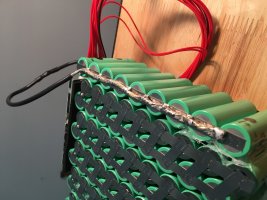
Yes, that is what I did for my pack. The advantage was also that I could then place cable on top, bend/crimp the strip around the bare cable and then soldered it. That way it almost ends up looking like being a full crimp joint, maximises the contact area and offers a nice smooth flat to circular profile. Bit of heat shrink over the top and looks great as well.....


image_swddmo.jpg
 
I would take 2 or more pieces of 12-10 AWG silicone lead and solder them well to nickle strips and attach those to the positive side in parallel... I would then combine all of that to a larger 8 or 6 awg welding cable. You can either use a buss bar or crimp all the conductors into a larger Anderson lug and have a quick disconnect for that.
 
"..... The advantage was also that I could then place cable on top, bend/crimp the strip around the bare cable and then soldered it. That way it almost ends up looking like being a full crimp joint, maximises the contact area and offers a nice smooth flat to circular profile. Bit of heat shrink over the top and looks great as well....."

That is a very interesting idea. I will practice it a few times on a smaller batter pack to ensure I can do it. I really appreciate the information.


completelycharged said:
WOW - I like the spot welder in the vid !

If you have nickel strips (and a spot welder) then just extend the strips away from the cells so that you can solder without heat transfer to the cells.

In your image I would have put 2 strips across the top and then 3 or 4 strips off to the side (up in the image) to solder to rather than solder directly onto the top of the cells..

The base/top of the pack is then completely flat and the connections are on the sides, this may be easer to box/fit.

If you have a large current then double/tripple the strip to the wiring or take off at each end.

In my 10s4p I ended up spot welding 2 layers of strip between cells and 3 layers for the end connections at just one end of the pack.

CrimpDaddy said:
I would take 2 or more pieces of 12-10 AWG silicone lead and solder them well to nickle strips and attach those to the positive side in parallel... I would then combine all of that to a larger 8 or 6 awg welding cable. You can either use a buss bar or crimp all the conductors into a larger Anderson lug and have a quick disconnect for that.

This is very helpful. I will give it some thought and proceed carefully. Thanks for taking the time to respond to my question.
 
WernerBecker said:
This is how I did last year ??

???? Please elaborate
 
@Completely charged, where did you get those 26650s?

Mind to share who is your seller?
 
Back
Top