Cherry67
Member
- Joined
- May 13, 2018
- Messages
- 518
Hi to all, into my ongoing project of building a small powerwall battery bank something else has come in between.
I have bought a medium (european style) mobile home. Is quite fully, but more or less standard equipped. The interesting infos regarding my coming question for the community are:
- solar panels 200 W
- 2 batterys 12 V 90 Ah AGM, one for the car, one for the home
- both are loaded by line , both are loaded by driving/Motor, both are loaded by solar (as usual)
- during "housing" only the home battery is used, the car battery stays undischarged (as usual)
- Sat TV, frigo, light, small inverter at 12 V (600 W) for occasional use,
- plus heating which uses about 50 Watts for the vents if in use.
We would like to be able to get through for a few days without line.
For all favourable situations the home battery might just be sufficient, but if we need heating, if its raining (no sun) for a few days the fun might come to an end very quickly.
It is clear that any sized bigger battery might come to an end sometimes as well, but i want to have at least a bit more capacity as the above mentioned 12 V 90 Ah. (the backup is line current or the motor or a generator).
The options are:
- another 12V 90 Ah AGM battery, there is a place for it (250 $)
- another 12 V 90 AH LiFePo, might fit into the place, (1000 $)
- something else.
I do not like the AGM, these are sensible leads, can only be used 50 % capacity or degrade quick, and it is very heavy.
I do not like the LiFePo, because it either has to live with the voltage levels allowed for the AGM (when in parallel), and for the price.
(and LiIon cannot be directly used, because the Voltage leves are wrong for 3s and 4s to be paralleled to Lead)
But i have 5 kWh in Liion around here already. In 10sxp Blocks, with 36 Volts.
In searching for a concept to implement that i have to take in account the 12 V level of the car, the already complex situation of energy supply ( 3 sources for energy), the complex management of the batterys (load both, protect the car bat), and so on.
I thought through many possible configurations, using the higher Voltage for inverters, adding charger from solar and line for the 36 V, and so on.
In the end, it helped to define my problem to be solved, i nailed it down to
- i need additional capacity
- i do not need high(er) wattage. (the inverter is sufficient and can stay at 12 volt)
- Basically the car has no "structural" problem of the environment, its just missing home batt capacity.
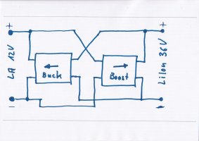
So i came to the strange concept of just a "capacity enhancer", which will be connected in parallel to the home battery, and nothing else.
[concept]
The enhancer supervises the home battery and does one of the following three things (as long as its own capacity lasts):
- on 12.8 Volt of the home batt it does nothing
- below 12.7 V of the home batt the enhancer starts to supply increasing current to the home batt with a linear correlation to lower voltages. In effect t takes the load which "obviously" drops the batts voltage, limited to 10 Amps.
- over 12.9 enhancer start to surge energy from the home batt (as well limited to 10 Amps), as well with a somehow linear correlation, because the battery is "obviously" fed.
- If the enhancer is empty, the AGM has to supply the load alone, and will be discharged then - as last in the row.
- If the enhancer is full, the charger can fully load or "occasional balance" the AGM as usual.
So, in "Normal use", the AGM stays mostly full (which it likes), the capacity is taken to and from the enhancer, cycling it. That increases lifetime of the AGM.
Shorttime high loads (inverter) need help from the AGM over 10 Amps, discharging it, but it will not be much.
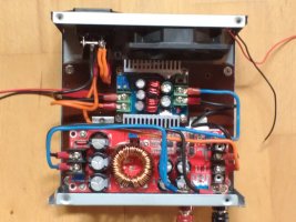
In summary, i need just the Enhancer batt and a bidirectinal inverter, controlled to above rules. I have no complex connection to the mobiles circuitry, the circuitry or its parameters must not even be changed. There ar some losses of energy, because it goes through the enhance inverters twice. But, i do not have limited resources of energy, i have limited resources of STORED energy, so no problem there).
It looks like i can get 2-3 kWh plus two standard Alipress inverters with an Arduino in a PC case, and have 3-5 times the energy of an AGM for half the weight.
My questions so far are:
- any comments on the concept ?
- are there circuits or supplies, which can just be used for the inverters functionality i need, or is that an issue to be build by myself?
(Just to mention, i can build that, but in general i would not if i can buy things. )
(Just to mention, if a current sensor/Feed through can measure the current of the Home battery, the regulation/control can be made even more easily and more sophistically. A feed through current transformer is imho no change of the cars circuit).


