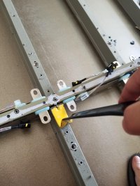
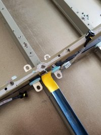
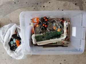
I currently have a 13kW (Peak) solar system that's grid tried using Enphase micro inverters, after doing a ton of research on energy storage for existing grid tied systems I ended up going with the same process Tesla uses with the PW. AC Coupling, it's not as efficient as DC coupling but I'm not about to re-wire all the modules on the roof.
That being said, the inverter i'll be using for this is:
12000 Watt Inverter | Pure Sine Wave 48V 12KW Inverter Charger
For the storage I bought a Tesla 60kW battery pack which I took apart.I came up with a quick mock up of the wiring for the system.

Externally there was no signs of damage or flooding and the casing matches what I bought so that's a good sign.

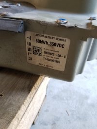
The first thing I did was open the "rear" of the battery to get a voltage, the place I bough it from said the pack was at 90% before they removed it from the car.
The 2 inside poles on the contactors gave me 297v ( (297/14)/6 = 3.53 per parallel cell, it looks like it wasn't quite 90% but it was still within range.
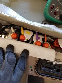

Now that I had verified a good voltage it was time to open it up. I went to remove the fuse (this was just for my own OCD as the fuse only disconnects the modules from the contactors, the battery bus bar is still live) and had my first encounter with this tar like glue they put all over the fuse lid.
I tried to scrape it, cut it, push but in the end a wire wheel was the best solution to find the lip of the lid under which to get under to pry up.

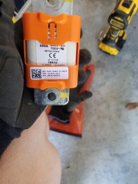
I wasn't playing around with removing the fuse, even though my multimeter said the negative of the batteries wasn't tied to the casing of the pack I double gloved to pull the bolts and the fuse itself.
Then came the process of removing way too many bolts
These go through the holes in the casing of the modules themselves and help keep the packs down tight to the pack casing (8mm)
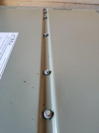
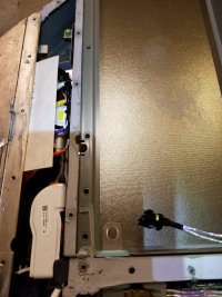
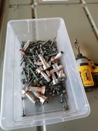
These hold down the perimeter of the pack down, in some areas they're totally covered with that grey glue. I ended up just pushing down on the glue and I got enough bite to remove it (T25). There is 2 flavors of these btw, the pictured are the non-security ones, near the hump and for the use they were all security T25.

These big guys are used to align the pack to the frame, they weren't too hard to remove but I didn't have an Alan key big enough so I used a T55 torx, they weren't torqued down too hard so they came right out.
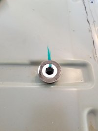
Souvenirs maybe?
With all the bolts out I started to pry up from the front near the hump and found the main difference on the 60kW pack.

Wait, is that....
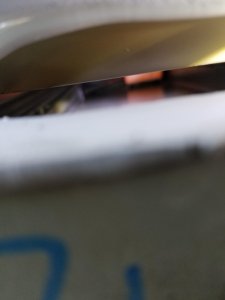
Yep it's empty, it makes sense since stacking 2 modules on the front would throw off the weight of the whole thing.

I sat and made sure there wasn't any parts of that fuse bus bars exposed prior to removing the hump, the last thing I wanted was to blow the cell level fuses due to my own stupidity.
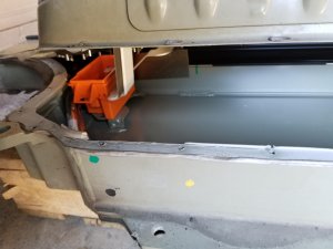
Finally I see the first pack.
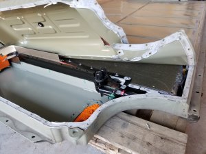
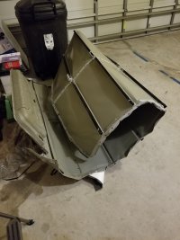
I realized that part of what made the cover so hard to lift was that it was folded down towards the pack which gives the lip rigidity so I went around the whole outside perimeter with some pliers and bent the lip upwards. This gave me the unintended benefit that the pliers acted as a lever to also pry up the 80% of the glue this made the next steps a lot easier (I did make sure I didn't apply too much pressure as I didn't want to indent the top cover part that protects the packs).
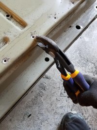

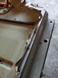
At this point I felt like I was opening a giant can of sardines
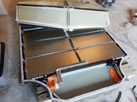
When I got to the end I ran into an issue. It looks like whoever put this pack together got a little overzealous with the glue and it got on to the module covers so I had to cut the glue to release the plastic cover (this glue crap is really strong, it's weird because it's soft like silicone but holds like gorilla glue)

Finally getting some progress done. Right on time to head to Lowes to get a hose to flush the coolat system. Call me crazy buy I don't want to mix liquids and 300VDC.
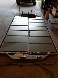
The closest size I could find was 1" but the coolant connectors are 1.14" (29mm) so I figured it'll stretch or I can use a heat gun to stretch it a bit. To my surprise a little force and it went right in. However, dumb me forgot to put something on the connector to keep the valve open.
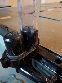
Let's try this again, this time I took a piece of the grey glue from the pack, pushed down the valve on the pack and placed it in between to keep the valve open as the valve would block the exit of fluid (I did this for the other valve as well but didn't take a picture)


So far so good, but I did run into a couple issues. First since the hose had an ID of 1" my air compressor blower fitting wasn't air tight which was allowing a ton of air to escape slowing down the process. Second I'm sure you can see, getting the fluid past the parabola of the hose without it going back inside. I got the majority of fluid out but a bit wouldn't make it across.
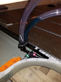
I then remembered that I had a 1" adapter for my shopvac so I used that to blow out the rest as it provided a much greater volume of air flowing through the system
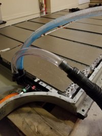
With all the coolant out it was time to remove the first module. All the videos and posts I was finding were either too vague on this step (or it was RichRebult cutting the coolant lines). Again liquid and HV = No for me so I started to look into how the connectors worked.
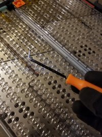
As it turns out they have a tab that you can put a pick underneath and they unlock from the module (Disregard the fact that the pics below I already removed the module (it was easier to picture the connectors that way).
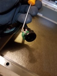

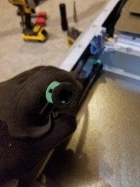
With the coolant hoses disconnected it was time to remove the BMS connector, this one just has a tab you press and then pull straight up. The connector is pretty fragile which makes it harder to remove.
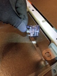
Finally, the first module is out. You can also clearly see where the module is missing some cells which makes it 4.3kW (4.3x14=60) instead of 5.2kW like the 85kW packs.

From here on out it was rinse and repeat, but by now it was late so I got 2 modules out and then had to stop.

We finished installing all the modules (and coolant connections). Then I was given the death stare because I had reached my max amount of time allotted to have the garage occupied by something other than cars so I had to do a rush clean job so the cars would fit. I still have more stuff to clean up so don't mind the messy garage.
Overall I think that gives me plenty of space to open my door even after I add some protective plexi to the front of the modules.

Back on the AC side I changed things a bit. I never liked the AC priority mode on the inverter (this mode makes the inverter a whole house UPS) since doing so would limit me to 12kW of loads plus solar combined without the grid and 19kW with the grid. Instead I wanted to switch over to the inverter when the power goes out or when my custom controller detects 0 solar production for 5 minutes.
To do this I was planning on using a manual transfer switch to either place the house on the grid or on backup power but I have found a much cleaner solution. Siemens makes a gen ready loads panel which you can install an ATS into.
https://www.amazon.com/gp/product/B005GLDETC/ref=ppx_yo_dt_b_asin_title_o03_s00?ie=UTF8&psc=1
https://www.amazon.com/gp/product/B004WL9B3U/ref=ppx_yo_dt_b_asin_title_o02_s00?ie=UTF8&psc=1
On one side you have the grid (and grid only loads) and on the other you have grid+backup loads (selected by the ATS). The great part about this setup is that I can wire my EV 14-50 to grid only (along with any loads I don't want backed up) and leave everything else backed up in the existing panel. This also makes me NEC compliant as code states that an ATS cannot have a mode where if a failure occurs could dual feed grid+backup (this could happen if a contactor welds shut due to loads)
I was testing the ATS last night and its operation is pretty basic, give it 12v +/- and trigger it to switch by giving -12v to the trigger input.

The inverter arrived, and damn this thing is heavy. 180lbs to be exact, what's worse is due to all the crap already on the wall of my garage I had to mount it almost 5 feet high, so how do you get 180 lbs up a wall by yourself?
Yea ratchet straps and a ladder will do.

Each strap could do 480lbs but I needed the whole thing to go up level since the transformer is at the top and make the whole thing top heavy

Finally, after what seemed like forever I reached the mounting holes.

It was after this that I noticed that it's 1/4" low on one side making the inverter not be level with the ground, but my OCD will have to suck it up because I'm not about to take that thing off the wall ... Ever.
Over on the electrical boxes, I got the ATS panel mounted and started running the conduit between the ATS, loads panel and the inverter. PVC conduit is soo much easier to work with than EMT, I used EMT on my solar install since I didn't like the idea of using plastic on the roof and the wire gauges were pretty small, but the wiring for this is all #3, #1 and #0/1 so nothing below 2" conduit would keep in code compliance for conduit fill. They had 2" EMT available at my local supplier but bending 3/4 was hard enough, I'd have to rent a hydraulic bender just for that so PVC instead it is.
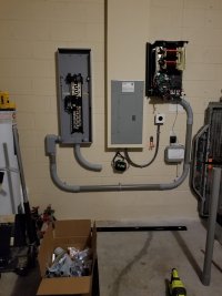
I needed to figure out a way to cleanly get the AC wiring into the inverter since it doesn't really have a cover of the wiring, so I moved on to DC again.
Since I switched to using the pack chassis as my "shelf" to mount the packs I had to figure out a way to mount the bus bars to the chassis itself. I bought some battery standoffs but for the life of me I couldn't find any M6 threaded rod locally. Luckily the bolts on the pack are pretty long so that gave me an idea.
Put the bolt on a vise, add a couple nuts (you'll see why later) then cut off the head and ta-da, instant threaded rod.
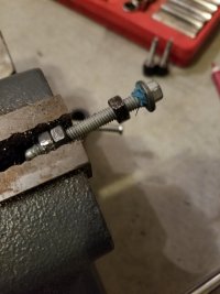
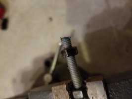
The reason for the nuts (other than to hold the bolt on the vise without damaging the threads, is to unscrew one over the area where the head was cut to fix any damaged threads during the cut.
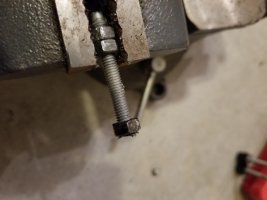

Add some red thread locker and they're all done.

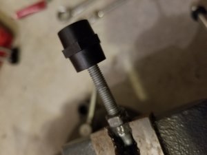
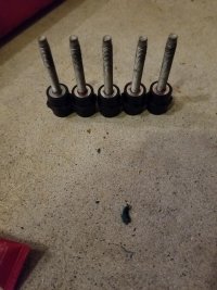

Back on the AC side I got the ATS wired and the loads panel connected to it.

Then came time to wire up the Inverter, since the ATS in the inverter can handle 19kW I calculated a #3 THHN (@60C) but the connectors on the inverter not only were too small but also didn't allow proper torque, So I ended up removing them and connecting directly to the breakers where the connectors were attached to.

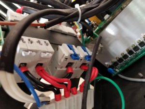
This makes me glad I re-wired the thing. This is how the neutral output came from factory.
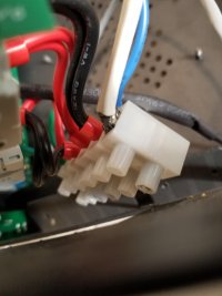
Then came time to run the wires to the inverter, 7 runs of #3, I thought it was going to be a pain, but with a little pull lube it went like a glove. (you can also see the bus bars temporarily mounted, I didn't take any pictures of marking the holes and drilling them out)

Finally here's all the wiring connected to the inverter through the knockout I made on the side of the inverter.

Since the AC side was all done I needed to get the DC buttoned up, the negative side wasn't getting a fuse I decided to mount the bar directly to the batteries by fabricating some Z bends out of the left over bus bars I had.

I had to mount my vise to the garage floor because I was literally tipping over my workbench.

All done Z bars bent, just needed to drill some holes in them.

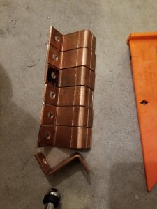
For the positive side, I wanted the ability to disconnect a module from the pack without removing the whole bus bar. So I reused from of the EXRAD 2/0 cable that I ripped out of the pack since it's apparently rated to over 1000A.
What do you do when your hydraulic crimper takes a dump on you and no one locally sells lug crimpers? You improvise.
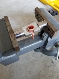
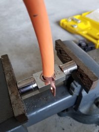
It took a bit longer longer using the vise but I got them all done.

Here are the bus bars all cleaned up and heat shrunk to prevent accidental shorts.
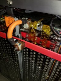
Here's how the negatives are connected to the bus bar (this may change since I noticed that a module could easily be shorted while connecting the opposite module, I may add fuses on the negative as well just in case)

On the positive the fuse holder is attached to the bus bar, then a 200A bussman fuse is in the between them protecting each module. The other benefit to mounting the modules to the busbars with a double layer of material is that I get to maintain the electrical capacity of the bar since now the material is thicker, this makes up for the mounting holes in the busbar.
For the past couple days I've been testing the pack/inverter and it's capability to sustain the house loads and I'm happy to report that I haven't ran into any major issues.
The first day I turned on the system and failed the house over to the pack I thought I had caused a brown out that damaged the AC compressor capacitor. In the end I just had to have patience since the manual failover caused the compressor to shut off inadvertently the Ecobee was doing a 300 second delay to allow cool down before starting it.
I've ran the house on the battery from the moment I got up to night time (I work from home) and I used about 25% and I didn't even have all 14 modules connected (only 8). So I think when I AC couple battery capacity won't be a problem, It looks like it would take a few days of no sunlight whatsoever to fully drain the pack.
Here's where the battery sat that evening. kWh is on the green side because the battery is charging back up using the internal charger from the grid. (I still need to AC couple my solar into the ATS panel, it's rained every damn day this month)
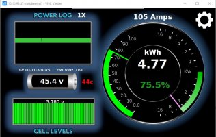
I also modified some of the Grafana dashboards to display the most relevant information in a prettier format.

Although the inverter can handle the LRA of my compressor it does cause the lights to blip and my UPSs to beep. Call me crazy but I'd rather not induce brown outs when possible. This led me down the hell hole that I call HVAC companies.
I must have called at least 6 HVAC local suppliers who all told me:
"Sorry we can't sell to home owners"
That crap annoys the ever living shitout of me, even more when I call a contractor to get it done since they're running this nice little monopoly and they don't even know what I'm talking about.
I finally got fed up and ended up buying it online from a marine distributor in Miami, Since soft starts are used in RVs and boats it seems they carry them and don't mind actually selling the products they carry, go figure.
Since I'm currently not AC coupled, and sometimes (like at night) I won't be I wanted to be able to control the internal charger on the inverter, I can use the EVTV BMS controller control the bottom end and disconnect the battery if it gets below my set threshold but the top end I can't do since the BMS controller disconnects the battery from the inverter and won't reconnect it without a human touch it means it would leave the pack disconnected if I had the BMS controller not set to the same top end SOC as the inverter.Secondly the inverter seems to want to use fully charge (4.2V per cell) and discharge (3V per cell) the pack which is not what I want since lithium doesn't like to fully charge and fully discharge.
So knowing I could control the bottom end with the BMS and the AC coupled charging using the BMS, all I had left was to control the grid tied charger built into the inverter. Here's when I had to get custom, since the inverter doesn't have an interface I had to go poking to see what I could find. Luckily I found that if i set the battery type rotary knob to 0 it would disable the grid tied charger (9 is lithium).

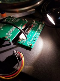
Once I had the board out of the inverter I proceeded to map the rotary dip switch contacts when set to 0 or 9.

Since it had no visible part numbers I couldn't pull up a spec sheet so I used a trusty multi meter in diode mode to figure out the connections, after scratching off some of the comformal coating I found out that connecting 2 pins to the common was the equivalent of setting the dial to 9. This means I can leave the dial always on 0 and use a micro controller and relay to turn on and off the charger according to the battery SOC.
I used some shielded cable I had to solder some connections to the board
This also opens the door to StormWatch mode when using the NOAA API
API Web Service
So after a very long post that's where I stand. The pack works, the inverter switches to battery mode fine, I have plenty of capacity (way more than the 2 PWs Tesla wantd to sell mewould have given me), I can run just about every load (except large concurrent loads like my S charging at full amps and the dryer but I can move my 14-50 to grid only or lower the charging amps on the car and who runs the dryer during a power outage anyways).
Now it's just final details on controllers and some custom software to control it all, oh and AC coupling my solar which isn't a big deal.
That being said, the inverter i'll be using for this is:
12000 Watt Inverter | Pure Sine Wave 48V 12KW Inverter Charger
For the storage I bought a Tesla 60kW battery pack which I took apart.I came up with a quick mock up of the wiring for the system.

Externally there was no signs of damage or flooding and the casing matches what I bought so that's a good sign.


The first thing I did was open the "rear" of the battery to get a voltage, the place I bough it from said the pack was at 90% before they removed it from the car.
The 2 inside poles on the contactors gave me 297v ( (297/14)/6 = 3.53 per parallel cell, it looks like it wasn't quite 90% but it was still within range.


Now that I had verified a good voltage it was time to open it up. I went to remove the fuse (this was just for my own OCD as the fuse only disconnects the modules from the contactors, the battery bus bar is still live) and had my first encounter with this tar like glue they put all over the fuse lid.
I tried to scrape it, cut it, push but in the end a wire wheel was the best solution to find the lip of the lid under which to get under to pry up.


I wasn't playing around with removing the fuse, even though my multimeter said the negative of the batteries wasn't tied to the casing of the pack I double gloved to pull the bolts and the fuse itself.
Then came the process of removing way too many bolts
These go through the holes in the casing of the modules themselves and help keep the packs down tight to the pack casing (8mm)

These hold down the perimeter of the pack down, in some areas they're totally covered with that grey glue. I ended up just pushing down on the glue and I got enough bite to remove it (T25). There is 2 flavors of these btw, the pictured are the non-security ones, near the hump and for the use they were all security T25.

These big guys are used to align the pack to the frame, they weren't too hard to remove but I didn't have an Alan key big enough so I used a T55 torx, they weren't torqued down too hard so they came right out.

Souvenirs maybe?

With all the bolts out I started to pry up from the front near the hump and found the main difference on the 60kW pack.

Wait, is that....

Yep it's empty, it makes sense since stacking 2 modules on the front would throw off the weight of the whole thing.

I sat and made sure there wasn't any parts of that fuse bus bars exposed prior to removing the hump, the last thing I wanted was to blow the cell level fuses due to my own stupidity.

Finally I see the first pack.

I realized that part of what made the cover so hard to lift was that it was folded down towards the pack which gives the lip rigidity so I went around the whole outside perimeter with some pliers and bent the lip upwards. This gave me the unintended benefit that the pliers acted as a lever to also pry up the 80% of the glue this made the next steps a lot easier (I did make sure I didn't apply too much pressure as I didn't want to indent the top cover part that protects the packs).


At this point I felt like I was opening a giant can of sardines

When I got to the end I ran into an issue. It looks like whoever put this pack together got a little overzealous with the glue and it got on to the module covers so I had to cut the glue to release the plastic cover (this glue crap is really strong, it's weird because it's soft like silicone but holds like gorilla glue)

Finally getting some progress done. Right on time to head to Lowes to get a hose to flush the coolat system. Call me crazy buy I don't want to mix liquids and 300VDC.

The closest size I could find was 1" but the coolant connectors are 1.14" (29mm) so I figured it'll stretch or I can use a heat gun to stretch it a bit. To my surprise a little force and it went right in. However, dumb me forgot to put something on the connector to keep the valve open.

Let's try this again, this time I took a piece of the grey glue from the pack, pushed down the valve on the pack and placed it in between to keep the valve open as the valve would block the exit of fluid (I did this for the other valve as well but didn't take a picture)


So far so good, but I did run into a couple issues. First since the hose had an ID of 1" my air compressor blower fitting wasn't air tight which was allowing a ton of air to escape slowing down the process. Second I'm sure you can see, getting the fluid past the parabola of the hose without it going back inside. I got the majority of fluid out but a bit wouldn't make it across.

I then remembered that I had a 1" adapter for my shopvac so I used that to blow out the rest as it provided a much greater volume of air flowing through the system

With all the coolant out it was time to remove the first module. All the videos and posts I was finding were either too vague on this step (or it was RichRebult cutting the coolant lines). Again liquid and HV = No for me so I started to look into how the connectors worked.
As it turns out they have a tab that you can put a pick underneath and they unlock from the module (Disregard the fact that the pics below I already removed the module (it was easier to picture the connectors that way).


With the coolant hoses disconnected it was time to remove the BMS connector, this one just has a tab you press and then pull straight up. The connector is pretty fragile which makes it harder to remove.

Finally, the first module is out. You can also clearly see where the module is missing some cells which makes it 4.3kW (4.3x14=60) instead of 5.2kW like the 85kW packs.

From here on out it was rinse and repeat, but by now it was late so I got 2 modules out and then had to stop.

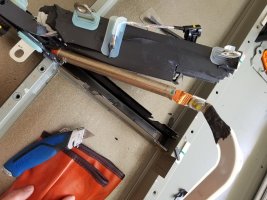
I continued pulling all the modules off the pack, as I finished off the driver side I got to the last module which has a busbar which connects back to the fuse housing. Due to this I decided to play it safe and leave the 2 front modules for last in case I couldn't pull the busbar without shorting it. I figured blown fuses on 2 modules is better than 8 modules (later on I'd come to realize this was the right decision).
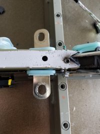
Moving to the back of the pack, the bars that hold the modules to the pack chassis are held down with that damn glue plus more torx screws, this time T30
Remember I said T30? Well I could only find the socket T30 instead of my screw gun bit and this clearly isn't going to work.
After some digging I found my bits and this is what it looks like with the bar removed
Removing the BMS connector was always a pain since I had to get awfully close to one of the metal pieces so I modified one of my picks, Last thing I wanted was for my pick to bridge off something and damage a BMS board since I plan on using those boards.
Almost done.
All I had left was the last 2 modules at the front, and it's a good thing I left them for last. Remember how I mentioned that someone got a little too happy with the glue gun? Yea well both of these modules were a pain to remove, the plastic sheet on the bottom was glued to the frame so I had to enroll my GF to help me by holding the module while I freed the tray from the glue. Needless to say I didn't take any pictures of that cause I only had 2 hands and I was already getting the death stare because I was taking too long freeing the trays.
Where are those damn early morning scrappers when you need one?
By the following day I had all the modules out and it was now time to remove all the non-metal pieces so a scrapper would either take it or I could drop it off to be recycled.
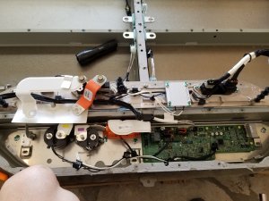
Here's what's underneath the back of the pack, to the left are the contactors , busbars leading to the HV connector, the pre-charge resistor, and BMS connectors to the BMS mother card.
As I started to remove busbars and cabling I noticed something funky, can you see it?
Yea that's not black plastic, that's ALL silicone, it looks like they put the busbars, BMS harness and HV cable in place then they flood the middle compartment with silicone. Yea things got messy real quick.
After removing the cabling for the first 4 modules I noticed that the middle channel was covered by metal, at this point I was ready to tell a scrapper you deal with it. Until I noticed that the metal channel was held down by 8mm nuts.
After removing all the nuts I used some leverage to get the metal casing off the silicone (yea they put it down while the silicone is still wet). Yes I'm wearing sandals because safety at 8 AM on a Saturday doesn't apply in FL heat plus all the heavy stuff was already out of the way.
I noticed that the EV cable was encased in what used to be a pipe of that same material they use for the module covers. It looks like either a fire retardant or to prevent heat from escaping the cable and damaging the tomb of silicone.
Battery shunt was attached to the end of the EV cable
Here's the brand and type of EV cable used in the middle channel, it looked like 2/0AWG.
The aftermath of the middle channel clean out.
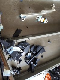
Everything else that came out of the pack that wasn't a module or the coolant loop.
At this point I was starting to think about how I would mount the packs in my garage, maybe build a rack like Jason Huges did, or maybe use an enclosure. Then I looked down and realized I'm stupid I have the perfect thing, since I don't have a lot of space in my garage and the busbars are out of the pack chassis now it's just a big case battery holder. soooo....
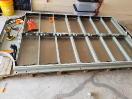
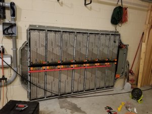
Yea it's mounted to the wall now. Well not hanging from the wall since that much weight would be problematic (even on brick) it basically sits on the ground and the 7 bolts on the top keep it from tipping over, each bolt can hold 1k lbs so I'm pretty sure it won't go anywhere. Next is testing the coolant loop and make sure there is no leaks on it as I do plan on using it (FL garages get pretty hot) hence why I didn't remove it (I did put on real shoes for this step).
We finished installing all the modules (and coolant connections). Then I was given the death stare because I had reached my max amount of time allotted to have the garage occupied by something other than cars so I had to do a rush clean job so the cars would fit. I still have more stuff to clean up so don't mind the messy garage.
Overall I think that gives me plenty of space to open my door even after I add some protective plexi to the front of the modules.

Back on the AC side I changed things a bit. I never liked the AC priority mode on the inverter (this mode makes the inverter a whole house UPS) since doing so would limit me to 12kW of loads plus solar combined without the grid and 19kW with the grid. Instead I wanted to switch over to the inverter when the power goes out or when my custom controller detects 0 solar production for 5 minutes.
To do this I was planning on using a manual transfer switch to either place the house on the grid or on backup power but I have found a much cleaner solution. Siemens makes a gen ready loads panel which you can install an ATS into.
https://www.amazon.com/gp/product/B005GLDETC/ref=ppx_yo_dt_b_asin_title_o03_s00?ie=UTF8&psc=1
https://www.amazon.com/gp/product/B004WL9B3U/ref=ppx_yo_dt_b_asin_title_o02_s00?ie=UTF8&psc=1
On one side you have the grid (and grid only loads) and on the other you have grid+backup loads (selected by the ATS). The great part about this setup is that I can wire my EV 14-50 to grid only (along with any loads I don't want backed up) and leave everything else backed up in the existing panel. This also makes me NEC compliant as code states that an ATS cannot have a mode where if a failure occurs could dual feed grid+backup (this could happen if a contactor welds shut due to loads)
I was testing the ATS last night and its operation is pretty basic, give it 12v +/- and trigger it to switch by giving -12v to the trigger input.

The inverter arrived, and damn this thing is heavy. 180lbs to be exact, what's worse is due to all the crap already on the wall of my garage I had to mount it almost 5 feet high, so how do you get 180 lbs up a wall by yourself?
Yea ratchet straps and a ladder will do.

Each strap could do 480lbs but I needed the whole thing to go up level since the transformer is at the top and make the whole thing top heavy

Finally, after what seemed like forever I reached the mounting holes.

It was after this that I noticed that it's 1/4" low on one side making the inverter not be level with the ground, but my OCD will have to suck it up because I'm not about to take that thing off the wall ... Ever.
Over on the electrical boxes, I got the ATS panel mounted and started running the conduit between the ATS, loads panel and the inverter. PVC conduit is soo much easier to work with than EMT, I used EMT on my solar install since I didn't like the idea of using plastic on the roof and the wire gauges were pretty small, but the wiring for this is all #3, #1 and #0/1 so nothing below 2" conduit would keep in code compliance for conduit fill. They had 2" EMT available at my local supplier but bending 3/4 was hard enough, I'd have to rent a hydraulic bender just for that so PVC instead it is.

I needed to figure out a way to cleanly get the AC wiring into the inverter since it doesn't really have a cover of the wiring, so I moved on to DC again.
Since I switched to using the pack chassis as my "shelf" to mount the packs I had to figure out a way to mount the bus bars to the chassis itself. I bought some battery standoffs but for the life of me I couldn't find any M6 threaded rod locally. Luckily the bolts on the pack are pretty long so that gave me an idea.
Put the bolt on a vise, add a couple nuts (you'll see why later) then cut off the head and ta-da, instant threaded rod.


The reason for the nuts (other than to hold the bolt on the vise without damaging the threads, is to unscrew one over the area where the head was cut to fix any damaged threads during the cut.


Add some red thread locker and they're all done.


Back on the AC side I got the ATS wired and the loads panel connected to it.

Then came time to wire up the Inverter, since the ATS in the inverter can handle 19kW I calculated a #3 THHN (@60C) but the connectors on the inverter not only were too small but also didn't allow proper torque, So I ended up removing them and connecting directly to the breakers where the connectors were attached to.


This makes me glad I re-wired the thing. This is how the neutral output came from factory.

Then came time to run the wires to the inverter, 7 runs of #3, I thought it was going to be a pain, but with a little pull lube it went like a glove. (you can also see the bus bars temporarily mounted, I didn't take any pictures of marking the holes and drilling them out)

Finally here's all the wiring connected to the inverter through the knockout I made on the side of the inverter.

Since the AC side was all done I needed to get the DC buttoned up, the negative side wasn't getting a fuse I decided to mount the bar directly to the batteries by fabricating some Z bends out of the left over bus bars I had.

I had to mount my vise to the garage floor because I was literally tipping over my workbench.

All done Z bars bent, just needed to drill some holes in them.


For the positive side, I wanted the ability to disconnect a module from the pack without removing the whole bus bar. So I reused from of the EXRAD 2/0 cable that I ripped out of the pack since it's apparently rated to over 1000A.
What do you do when your hydraulic crimper takes a dump on you and no one locally sells lug crimpers? You improvise.


It took a bit longer longer using the vise but I got them all done.

Here are the bus bars all cleaned up and heat shrunk to prevent accidental shorts.

Here's how the negatives are connected to the bus bar (this may change since I noticed that a module could easily be shorted while connecting the opposite module, I may add fuses on the negative as well just in case)

On the positive the fuse holder is attached to the bus bar, then a 200A bussman fuse is in the between them protecting each module. The other benefit to mounting the modules to the busbars with a double layer of material is that I get to maintain the electrical capacity of the bar since now the material is thicker, this makes up for the mounting holes in the busbar.

For the past couple days I've been testing the pack/inverter and it's capability to sustain the house loads and I'm happy to report that I haven't ran into any major issues.
The first day I turned on the system and failed the house over to the pack I thought I had caused a brown out that damaged the AC compressor capacitor. In the end I just had to have patience since the manual failover caused the compressor to shut off inadvertently the Ecobee was doing a 300 second delay to allow cool down before starting it.
I've ran the house on the battery from the moment I got up to night time (I work from home) and I used about 25% and I didn't even have all 14 modules connected (only 8). So I think when I AC couple battery capacity won't be a problem, It looks like it would take a few days of no sunlight whatsoever to fully drain the pack.
Here's where the battery sat that evening. kWh is on the green side because the battery is charging back up using the internal charger from the grid. (I still need to AC couple my solar into the ATS panel, it's rained every damn day this month)

I also modified some of the Grafana dashboards to display the most relevant information in a prettier format.

Although the inverter can handle the LRA of my compressor it does cause the lights to blip and my UPSs to beep. Call me crazy but I'd rather not induce brown outs when possible. This led me down the hell hole that I call HVAC companies.
I must have called at least 6 HVAC local suppliers who all told me:
"Sorry we can't sell to home owners"
That crap annoys the ever living shitout of me, even more when I call a contractor to get it done since they're running this nice little monopoly and they don't even know what I'm talking about.
I finally got fed up and ended up buying it online from a marine distributor in Miami, Since soft starts are used in RVs and boats it seems they carry them and don't mind actually selling the products they carry, go figure.
Since I'm currently not AC coupled, and sometimes (like at night) I won't be I wanted to be able to control the internal charger on the inverter, I can use the EVTV BMS controller control the bottom end and disconnect the battery if it gets below my set threshold but the top end I can't do since the BMS controller disconnects the battery from the inverter and won't reconnect it without a human touch it means it would leave the pack disconnected if I had the BMS controller not set to the same top end SOC as the inverter.Secondly the inverter seems to want to use fully charge (4.2V per cell) and discharge (3V per cell) the pack which is not what I want since lithium doesn't like to fully charge and fully discharge.
So knowing I could control the bottom end with the BMS and the AC coupled charging using the BMS, all I had left was to control the grid tied charger built into the inverter. Here's when I had to get custom, since the inverter doesn't have an interface I had to go poking to see what I could find. Luckily I found that if i set the battery type rotary knob to 0 it would disable the grid tied charger (9 is lithium).

Once I had the board out of the inverter I proceeded to map the rotary dip switch contacts when set to 0 or 9.

Since it had no visible part numbers I couldn't pull up a spec sheet so I used a trusty multi meter in diode mode to figure out the connections, after scratching off some of the comformal coating I found out that connecting 2 pins to the common was the equivalent of setting the dial to 9. This means I can leave the dial always on 0 and use a micro controller and relay to turn on and off the charger according to the battery SOC.
I used some shielded cable I had to solder some connections to the board

This also opens the door to StormWatch mode when using the NOAA API
API Web Service
So after a very long post that's where I stand. The pack works, the inverter switches to battery mode fine, I have plenty of capacity (way more than the 2 PWs Tesla wantd to sell mewould have given me), I can run just about every load (except large concurrent loads like my S charging at full amps and the dryer but I can move my 14-50 to grid only or lower the charging amps on the car and who runs the dryer during a power outage anyways).
Now it's just final details on controllers and some custom software to control it all, oh and AC coupling my solar which isn't a big deal.


