LiFepo4 portable power station

AndrewBrown

New member
Joined
May 26, 2020
Messages
25
Hi Folks!

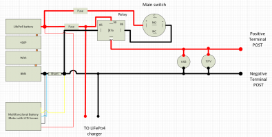
Greetings, I am planning to build portable power station for off grid camping. I drew the schematic and wanna ask you advice regarding attached scheme and connectivity of the components.

1. Is the scheme correct?
2. Where can I find option how to connect all wires together? Wich way is better and durable? (crimp connectors, soldering, or Wago pluggable connectors)
3. Is there are any other options for connection?
4. I'm planning that load shouldn't exceed 20A .
5. Where should I allocate the fuse?
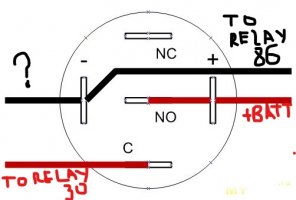
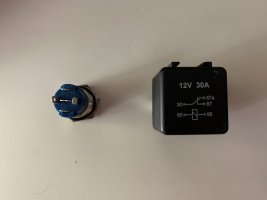
6. My main switch can hold 5A max, so I assume the I should use relay. How connect main switch with 5 legs to the relay which has 4 legs.


Thanks in advance for any help.
 

Attachments

  • VISIO_WGxZymysbt.png
    VISIO_WGxZymysbt.png
    56.7 KB · Views: 163
Looks good. what cells will you be using?
a relay is not need, Use a Dc circuit breaker/ dc switch rated for more than the load. Eliminating the relay and putting a heavy duty dc switch cuts down on points of failure. 4s LiFePo4 bms's come in various sizes 40-80A should do. I use a relay on my 4s LiFePo4 builds because I had the relays and for starting vehicles.
Later floyd
Thank you for your comment.

I purchased this cells: LiitoKala: Lii-70A 32700 3,2 v 7000mAh lifepo4. (https://www.aliexpress.com/item/329...exp_id=bb6974bf-623a-45c1-b6c4-28258aaa7d96-1).

As of BMS I purchased 3.2v LifePO4 BMS 4S (40A)
(https://www.aliexpress.com/item/33027173225.html?spm=a2g0o.productlist.0.0.67751112l4ki6E&algo_pvid=2751faef-8300-4274-838f-29a44a7fc329&algo_exp_id=2751faef-8300-4274-838f-29a44a7fc329-0)

Could you please show an example of heavy duty switch which can be allocated on the Pelican case? (I have attached the picture of the case with the components)
 

Attachments

  • IMG_4789.JPG
    IMG_4789.JPG
    2.1 MB · Views: 105
https://www.ebay.com/itm/324697520823? a Dc circuit breaker would work you can get single pole or double pole
a Dc circuit breaker would work
later floyd
Thank you for your advice. I'm really appreciated for your help. I have found a bunch of DC circuit breakers however they are all so bulky and didn't fit into my project. Can I still use on/off LED button (rated for 3Amps ) with relay? Or there are no other ways exept these bulky DC breakers ?
 
I use the anderson power pole connections all over the place. They are awesome!! I have a similar type of box that I built with 26650 in a 4s10p setup. I have a victron mppt inside too so I can plug in my portable panels and keep things going in camp for quite a while!
 
I second what was shared above about Anderson PP connectors. I have an AmmoBat I make with 18650 7s26p 24vdc. I have designed it for high 90amp load but also included a usb PD 60w port. I have a way overpriced anderson connector that is easy to install and I use for both the load and charging and I used Midnight Solar Breaker for safety and on/off switch. I am currently working on a new design that will use a custom designed BMS with build in on/off and safety functions.
 
These are the auto reset circuit breakers I been using. They are small and easy to mount. I used to use ATO fuses but when use constantly near there max rating they get very hot, these breakers can be use constantly near there max rating and just get warm.
If you are going to use fuses I recommend the larger ANL fuses but they take alot more space then the auto reset circuit breaker.

You can find these on ebay for about 8 dollars, they come in different size amp rating. For installation the copper(shorter) side goes to the battery.

a auto reset 20a.jpg

For crimping of smaller gauge ring terminals I recommend the IWS-16 crimper, it does a very good job. I payed about 25 dollars for it. I have different crimpers for different jobs.
a iws 16 crimpers.jpg
 
These are the auto reset circuit breakers I been using. They are small and easy to mount. I used to use ATO fuses but when use constantly near there max rating they get very hot, these breakers can be use constantly near there max rating and just get warm.
If you are going to use fuses I recommend the larger ANL fuses but they take alot more space then the auto reset circuit breaker.

You can find these on ebay for about 8 dollars, they come in different size amp rating. For installation the copper(shorter) side goes to the battery.

View attachment 25567

For crimping of smaller gauge ring terminals I recommend the IWS-16 crimper, it does a very good job. I payed about 25 dollars for it. I have different crimpers for different jobs.
View attachment 25568
Thank you
 
Does anybody know how properly connect the relay and my main switch? Pictures attached.

Thanks in advance
 

Attachments

  • IMG_4910.JPG
    IMG_4910.JPG
    2.5 MB · Views: 103
  • IMG_4912.JPG
    IMG_4912.JPG
    1.6 MB · Views: 99
Yes you wire the power to engage the relay via the swithc.

Example

85 to Ground
86 to the switch
switch to positive via fuse


Positive from battery to fuse to 30 on the relay and then you have the output.
 
Yes you wire the power to engage the relay via the swithc.

Example

85 to Ground
86 to the switch
switch to positive via fuse


Positive from battery to fuse to 30 on the relay and then you have the output.
Thank you for your advice. Could you please check attached diagram. It is correct?
 

Attachments

  • VISIO_cmeRsYavVD.png
    VISIO_cmeRsYavVD.png
    106.5 KB · Views: 116
Looks good!

I would have its own fuse for the charger and i would put the screen behind a fuse to :)

Basically never have anything connected to the battery with out the proper fuse for that application.
 
Looks good!

I would have its own fuse for the charger and i would put the screen behind a fuse to :)

Basically never have anything connected to the battery with out the proper fuse for that application.
Thank you. I'm really appreciate for your help.

I have finished the assembling. Nothing is exploded, and that really awesome! After I connect positive wire LCD screen is went ON and green LED indication on main switch is ON also. However, USB ports and 12V cigarette lighter socket are stays off even if I turn on the main switch. Could you show the right way to troubleshoot this?
 
Trace the wiring to the last spot on the wires to the usb/12v socket that has 12v would be how i would trouble shoot it.
Later floyd
 
Thank you, I found problem. I wrongly connect main switch (type of the main switch: 1NO/1NC). On the main switch I connected only to + and - and this gave me only LED indication and I totally forgot about NC, NO and C connectors on the main switch. I suppose this is root cause.
 
I think I found scheme connection main switch and relay. Is that correct?
 

Attachments

  • Inked19d431_LI.jpg
    Inked19d431_LI.jpg
    845.7 KB · Views: 87
I am not sure. Every Bms I have hooked up to a relay using the B- all three they have all had load connections and separate wires for the Positive and the negative control wires/ control connections clearly labeled. MY contactors(relays)are NO and the switches are SPST, while yours appears to be DPST have NC,NO depending on how you wire it. Can you get an SPST on off switch? Less complex fewer things to go wrong. It appears that you are using the relay to switch both pos. and neg.. Where I only switched one pole the- (negative) with the relay. My switch is on a positive wire from the battery Positive control . The negative wire comes from B- if the BMS cuts power it will cut power to the relay or the switch can cut power on the positive wire.
I think if you get a Single Pole Single Throw switch it would work. Course that might take some rewiring.
My head hurts now ouch

Later floyd
Will this SPST (https://www.ebay.com/itm/172209278629) work?
 
Last edited:
Back
Top